


4.35
ELECTRONIC FUEL INJECTION
4
9923142 - 2011 RANGER RZR / RZR S / RZR 4 Service Manual
© Copyright 2010 Polaris Sales Inc.
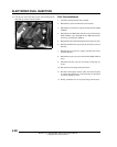
IGNITION COIL
Operation Overview
The ignition coil is used to provide high voltage to fire the spark
plugs. When the ignition key is on, DC voltage is present in
primary side of the ignition coil windings. During engine
rotation, an AC pulse is created within the crankshaft position
sensor for each passing tooth on the flywheel. The two-tooth gap
creates an “interrupt” input signal, corresponding to specific
crankshaft position. This signal serves as a reference for the
control of ignition timing. The ECU then calculates the time
interval between the consecutive pulses, and determines when
to trigger the voltage spike that induces the voltage from the
primary to the secondary coil windings to fire the spark plugs.
Ignition Coil / HT Lead Replacement
NOTE: Mark or note which ignition coil wire goes to
which cylinder and ignition coil post. The engine will
misfire if the spark plug wires are installed
incorrectly. The spark plug wires are marked with
PTO and MAG from the factory and should be
installed to the corresponding cylinder and ignition
coil post.
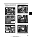
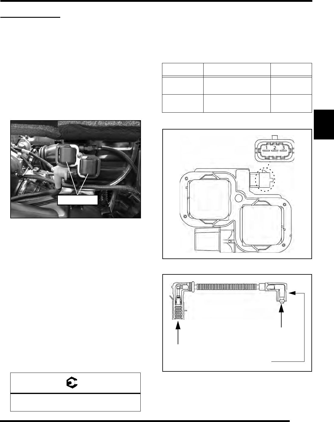
1. Remove the rear service panel to access the ignition coil.
2. Disconnect the ignition coil harness and remove the high
tension leads from the coil.
3. Remove the fastener retaining the ignition coil and remove
it from the vehicle. If replacing the high tension lead(s),
remove the other end of the lead(s) from the spark plug.
4. Install the new ignition coil and/or high tension lead(s).
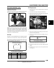
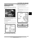
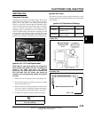
Ignition Coil Tests
The ignition coil can be tested by using an ohm meter. Use the
following illustration and specification table to test the ignition
coil resistance.
Primary Test
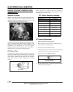
Secondary Test
= T
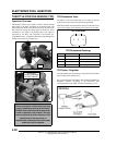
Ignition Coil Retaining Bolt Torque:
75 in. lbs. (8.5 Nm)
Ignition Coil
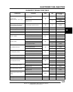
Ignition Coil Resistance Readings
Test Pin Connection Resistance
Primary
Between 1 & 2
Between 2 & 3
0.4
Secondary
Between High Tension
Lead End Caps
6.7k ± 5%
Measure Between
Connector Pins
0.4
Measure Between End Caps
6.7k ± 5%