


10.15
ELECTRICAL
10
9923142 - 2011 RANGER RZR / RZR S / RZR 4 Service Manual
© Copyright 2010 Polaris Sales Inc.
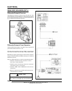
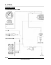
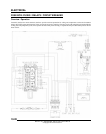
ALL WHEEL DRIVE COIL
Operation Overview
• When the AWD switch is “ON”, 12 VDC power is
present at the hub coil.
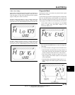
• If the criteria is met, the Engine Controller provides a
ground path (brown/white wire). When this occurs the
AWD icon should display in the instrument cluster.
• The AWD system must be grounded to operate.
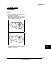
Diagnosing System Failures
• Verify the AWD switch is functional and that a
minimum of 11 volts is present at the hub coil.
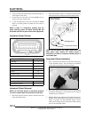
• Verify the AWD hub coil is functional. Test the AWD
hub coil using an ohm meter. See specifications below:
• Verify the wiring harness, wiring, connectors, connector
pins and grounds are undamaged, clean and connect
properly.
• Verify continuity of wire connections with a known
good volt/ohm meter.
IMPORTANT: Verify all wires and wiring connections
have been tested properly with a known good volt/
ohm meter before suspecting a component failure.
80% of all electrical issues are caused by bad/failed
connections and grounds.
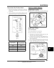
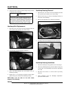
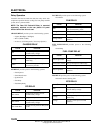
HEAD LIGHTS
Headlight Adjustment
The headlight beam is adjustable.
1. Place the vehicle on a level surface with the headlight
approximately 25 ft. (7.6 m) from a wall.
2. Measure the distance from the floor to the center of the
headlight and make a mark on the wall at the same height.
3. With the machine in Park, start the engine and turn the
headlight switch to on.
4. The most intense part of the headlight beam should be
aimed 8 in. (20 cm) below the mark placed on the wall in
Step 2.
NOTE: Rider weight must be included in the seat
while performing this procedure.
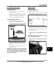
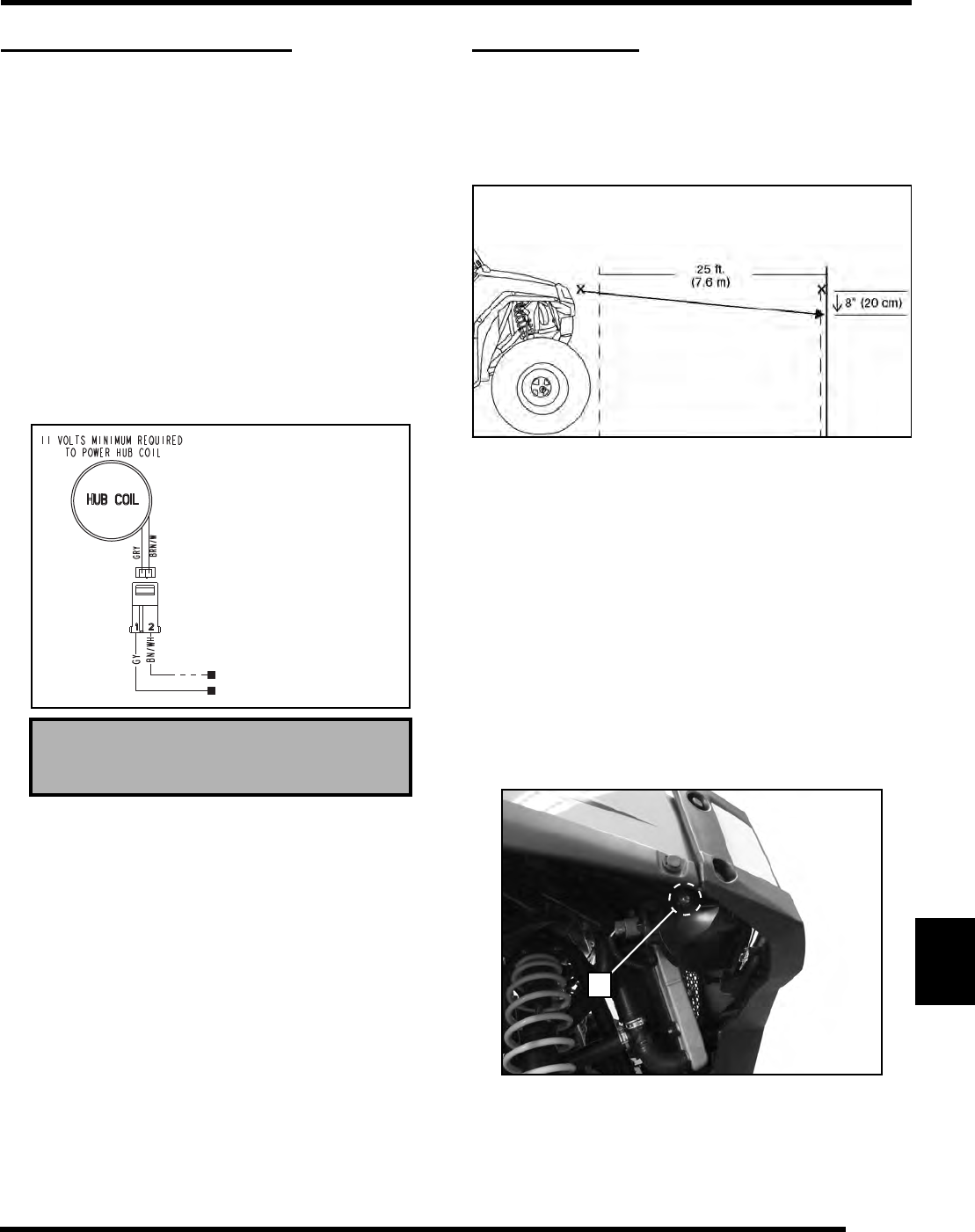
5. Adjust the beam to the desired position by loosening the
adjustment screw (A) and moving the lamp to the
appropriate height.
AWD Hub Coil Resistance:
24
± 5%
7HVW5HVLVWDQFH
5HDGLQJVVKRXOGEH
*<WR%1:+a2KPV
*<WR*URXQG1R&RQQHFWLRQ
A