


10.19
ELECTRICAL
10
9923142 - 2011 RANGER RZR / RZR S / RZR 4 Service Manual
© Copyright 2010 Polaris Sales Inc.
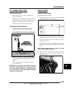
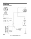
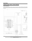
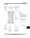
Fan Control Circuit Operation / Testing
Power is supplied to the fan via the Orange/Black wire when the
relay is ON. The ground path for the fan motor is through the
Brown harness wire. Refer to “RELAYS” later in this chapter
for more information on fan functions.
NOTE: The fan may not function or operation may
be delayed if coolant level is low or if air is trapped in
the cooling system. Be sure cooling system is full
and purged of air. Refer to Chapter 2 “Maintenance”
for cooling system information.
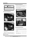
Fan Control Circuit Bypass Test
1. Disconnect harness from coolant temperature sensor on
the engine cylinder head (see Chapter 4 for location).
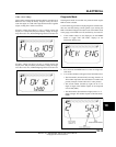
2. With the transmission in Park, start the engine. After a few
seconds, the fan should start running and the “Check
Engine” indicator should display on the instrument cluster.
This indicates all other components are working properly.
3. If the fan does not run or runs slowly, check the fan motor
wiring, ground, motor condition and mechanical relay for
proper operation. Repair or replace as necessary. If the fan
runs with the sensor harness disconnected, but will not turn
on when the engine is hot, check the coolant temperature
sensor and connector terminals.
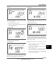
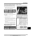
Coolant Temperature Sensor
The coolant temperature sensor can be tested using an ohmmeter
or voltmeter.
1. With the engine and temperature sensor at room
temperature (68
F = 20C), disconnect the harness.
2. With the meter in the ohms mode, place the meter leads
onto the sensor contacts.
3. Use the table Temperature / Resistance table to determine
if the sensor needs to be replaced.
NOTE: If the coolant temperature sensor or circuit
malfunctions the radiator fan will default to 'ON'.
EFI DIAGNOSTICS
EFI Component Testing
All EFI component information and diagnostic testing
procedures are located in Chapter 4.
Refer to Chapter 4 “Electronic Fuel Injection System (EFI)”
when diagnosing an EFI system or component.
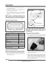
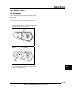
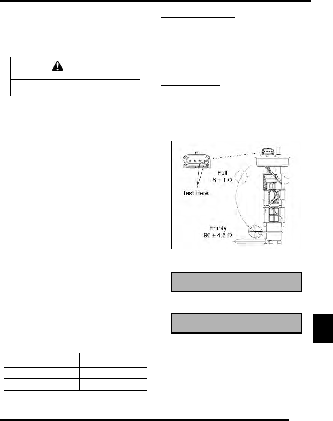
FUEL SENDER
Testing
1. Drain the fuel tank and remove it from the vehicle (see
Chapter 4).
2. Set the fuel tank on a flat surface. Using an Ohm meter,
measure the resistance of the fuel sender as shown below.
3. Allow the sender float to sit in the empty position and
compare to specification.
4. Slowly tilt the tank so that gravity moves the sender float
to the full position and compare to specification.
5. If the readings are out of specification, or if the reading is
erratic or LCD display “sticks”, check the following before
replacing the fuel pump assembly:
• Loose float
• Float contact with tank
• Bent float rod
If none of the conditions exist, the fuel sender assembly is faulty.
Replace the fuel pump assembly (see Chapter 4).
CAUTION
Keep hands away from fan blades during
operation. Serious personal injury could result.
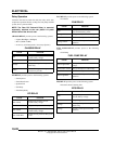
T
EMPERATURE F (C) RESISTANCE
68F (20 C) 2.5 k 6%
212
F (100 C) 186 2%
Fuel Sender - Empty: 90 ± 4.5
Fuel Sender - Full: 6 ± 1