


6.3
CLUTCHING
6
9923142 - 2011 RANGER RZR / RZR S / RZR 4 Service Manual
© Copyright 2010 Polaris Sales Inc.
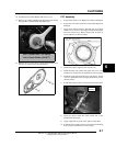
Driven Clutch Operation
Driven clutches primarily sense torque, opening and closing
according to the forces applied to it from the drive belt and the
transmission input shaft. If the torque resistance at the trans-
mission input shaft is greater than the load from the drive belt,
the drive belt is kept at the outer diameter of the driven clutch
sheaves.
As engine RPM and horsepower increase, the load from the
drive belt increases, resulting in the belt rotating up toward the
outer diameter of the drive clutch sheaves and downward into
the sheaves of the driven clutch. This action, which increases the
driven clutch speed, is called upshifting.
Should the throttle setting remain the same and the vehicle is
subjected to a heavier load, the drive belt rotates back up toward
the outer diameter of the driven clutch and downward into the
sheaves of the drive clutch. This action, which decreases the
driven clutch speed, is called backshifting.
In situations where loads vary (such as uphill and downhill) and
throttle settings are constant, the drive and driven clutches are
continually shifting to maintain optimum engine RPM. At full
throttle a perfectly matched PVT system should hold engine
RPM at the peak of the power curve. This RPM should be
maintained during clutch upshift and backshift. In this respect,
the PVT system is similar to a power governor. Rather than vary
throttle position, as a conventional governor does, the PVT
system changes engine load requirements by either upshifting or
backshifting.
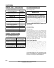
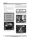
PVT Break-In (Drive Belt / Clutches)
A proper break-in of the clutches and drive belt will ensure a
longer life and better performance. Break in the clutches and
drive belt by operating at slower speeds during the 10 hours as
recommended (see Chapter 3 “Engine Break-In Period” for
break-in example). Pull only light loads. Avoid aggressive
acceleration and high speed operation during the break-in
period.
Maintenance / Inspection
Under normal use the PVT system will provide years of trouble
free operation. Periodic inspection and maintenance is required
to keep the system operating at peak performance. The
following list of items should be inspected and maintained to
ensure maximum performance and service life of PVT
components. Refer to the troubleshooting checklist at the end of
this chapter for more information.
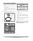
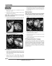
1. Belt Inspection.
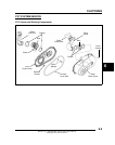
2. Drive and Driven Clutch Buttons and Bushings, Drive
Clutch Shift Weights and Pins, Drive Clutch Spider
Rollers and Roller Pins, Drive and Driven Clutch
Springs.
3. Sheave Faces. Clean and inspect for wear.
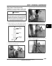
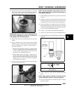
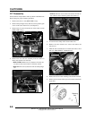
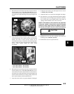
4. PVT System Sealing. Refer to the appropriate
illustration(s) on the following pages. The PVT system is
air cooled by fins on the drive clutch stationary sheave. The
fins create a low pressure area in the crankcase casting,
drawing air into the system through an intake duct. The
opening for this intake duct is located at a high point on the
vehicle (location varies by model). The intake duct draws
fresh air through a vented cover. All connecting air ducts
(as well as the inner and outer covers) must be properly
sealed to ensure clean air is being used for cooling the PVT
system and also to prevent water and other contaminants
from entering the PVT area. This is especially critical on
units subjected to frequent water forging.