


4.32
ELECTRONIC FUEL INJECTION
9923142 - 2011 RANGER RZR / RZR S / RZR 4 Service Manual
© Copyright 2010 Polaris Sales Inc.
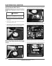
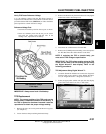
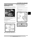
3. Loosen the TPS mounting screws (see Figure 4-31).
4. Rotate the TPS until your display reading is within
specification.
5. Retighten the TPS mounting screws and torque to
specification.
6. Verify voltage reading did not change. If voltage reading
is now out of specification, repeat steps 3 - 5.
7. Remove the shop towels from the intake boots and reinstall
the throttle body. Securely tighten the hose clamps.
8. Reinstall cargo box, rear service panel and seats (see
Chapter 5).
TPS Adjustment Using TPS Tester (PN 2201519-A):
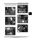
1. If Digital Wrench™ is unavailable, assemble the TPS
Tester according to the instructions. Refer to “TPS Tester
/ Regulator” for proper set-up and testing. Verify the 9 volt
tester battery is new.
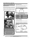
2. Plug the TPS Tester harness into the new TPS.
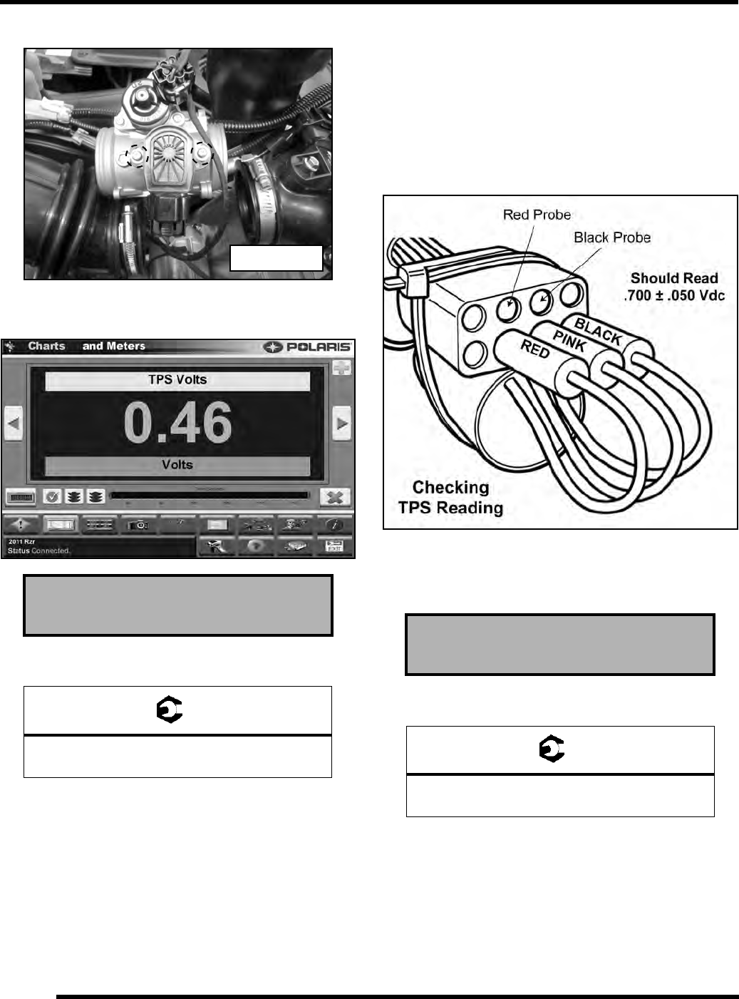
3. Set your voltmeter to read DC Volts. Insert the red and
black voltmeter probes into the test ports as shown.
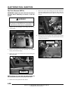
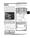
4. Loosen the TPS mounting screws (see Figure 4-31).
5. Rotate the TPS until your voltmeter reads within the
specification (see Figure 4-32).
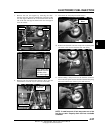
6. Retighten the TPS mounting screws and torque to
specification.
7. Verify voltage reading did not change. If voltage reading
is now out of specification, repeat steps 4 - 6.
8. Reconnect the vehicle harness to the TPS.
9. Remove the shop towels from the intake boots and reinstall
the throttle body. Securely tighten the hose clamps.
10. Reinstall cargo box, rear service panel and seats (see
Chapter 5).
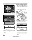
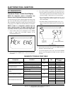
TPS Output Reading (Digital Wrench™):
0.46 ± 0.03 Vdc
= T
TPS Mounting Screws:
17.7 in. lbs. (2 Nm)
Figure 4-31
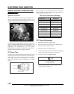
TPS Output Reading (TPS Tester):
.700 ± .050 Vdc
= T
TPS Mounting Screws:
17.7 in. lbs. (2 Nm)
Figure 4-32