


97
Detailed Operation
Typical Operational Scenario
The following scenarios makes the assumption that:
• The appropriate charts are available and geo-referenced
• The default ground zoom level is set to 0.5 nm
• The default air zoom level is set to “AUTO”
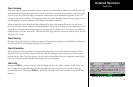
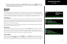
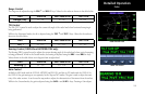
Typical Taxi Scenario
On power up and GPS position acquisition, the Custom Map Function will show the aircraft on the surface chart at a zoom level of 0.5 nm. The aircraft will be shown
relative to taxiways and runways throughout the taxi procedure.
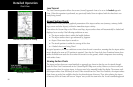
Typical Takeoff Scenario
On takeoff roll, when the aircraft reaches the air/ground speed threshold, the display will automatically transition to the en route zoom mode of “AUTO” and adjust
the display to show the current destination waypoint.
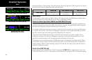
Typical Approach Scenario
Setting the destination waypoint to the destination airport on the GPS navigation system and pressing LOAD CHART from the Custom/IFR Map will present the
destination airport in the selection list. Selecting this airport will then bring up the approach charts that are available for that airport, which can then be loaded by
pressing the LOAD “smart” key.
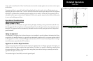
Typical Landing Scenario
With an approach chart being “flown,” upon touchdown and rollout, the chart will be unloaded and the map will automatically switch to the airport surface chart
with the zoom level set to 0.5 nm.
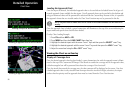
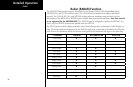
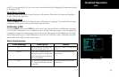
Autoloading
The GNS 480-series GPS navigator can request the MX20 to load a chart so you only need to select a chart on one device. In most cases, the MX20 will have the same
chart in its database and will display the selected chart.
On occasion, the MX20 may not be able to find the selected chart. When this happens, the following will be displayed in the MSG function: “Autoload chart not
found. Load manually.” The MX20 may also find multiple charts. When this happens, the following will be displayed in the MSG function: “Multiple Autoload charts
found. Load chart manually.” The desired chart can be loaded using the steps starting on page 92.
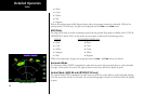
Chart View