


TMS320VC5402
FIXEDĆPOINT DIGITAL SIGNAL PROCESSOR
SPRS079E – OCTOBER 1998 – REVISED AUGUST 2000
50
POST OFFICE BOX 1443 • HOUSTON, TEXAS 77251–1443
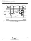
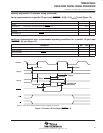
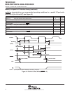
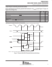
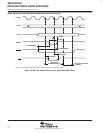
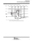
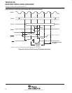
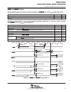
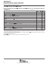
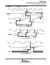
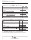
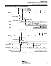
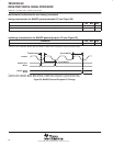
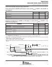
reset, BIO, interrupt, and MP/MC timings
timing requirements for reset, BIO
, interrupt, and MP/MC [H = 0.5 t
c(CO)
] (see Figure 22, Figure 23,
and Figure 24)
MIN
MAX
UNIT
MIN MAX UNIT
t
h(RS)
Hold time, RS after CLKOUT low 0 ns
t
h(BIO)
Hold time, BIO after CLKOUT low 0 ns
t
h(INT)
Hold time, INTn, NMI, after CLKOUT low
†
0 ns
t
h(MPMC)
Hold time, MP/MC after CLKOUT low 0 ns
t
w(RSL)
Pulse duration, RS low
‡§
4H+5 ns
t
w(BIO)S
Pulse duration, BIO low, synchronous 2H+2 ns
t
w(BIO)A
Pulse duration, BIO low, asynchronous 4H ns
t
w(INTH)S
Pulse duration, INTn, NMI high (synchronous) 2H ns
t
w(INTH)A
Pulse duration, INTn, NMI high (asynchronous) 4H ns
t
w(INTL)S
Pulse duration, INTn, NMI low (synchronous) 2H+2 ns
t
w(INTL)A
Pulse duration, INTn, NMI low (asynchronous) 4H ns
t
w(INTL)WKP
Pulse duration, INTn, NMI low for IDLE2/IDLE3 wakeup 10 ns
t
su(RS)
Setup time, RS before X2/CLKIN low
¶
5 ns
t
su(BIO)
Setup time, BIO before CLKOUT low 7 10 ns
t
su(INT)
Setup time, INTn, NMI, RS before CLKOUT low 7 10 ns
t
su(MPMC)
Setup time, MP/MC before CLKOUT low 5 ns
†
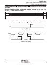
The external interrupts (INT0–INT3, NMI) are synchronized to the core CPU by way of a two-flip-flop synchronizer which samples these inputs
with consecutive falling edges of CLKOUT. The input to the interrupt pins is required to represent a 1-0-0 sequence at the timing that is
corresponding to three CLKOUT sampling sequences.
‡
If the PLL mode is selected, then at power-on sequence, or at wakeup from IDLE3, RS
must be held low for at least 50 µs to ensure
synchronization and lock-in of the PLL.
§
Note that RS
may cause a change in clock frequency, therefore changing the value of H.
¶
Divide-by-two mode