


TMS320VC5402
FIXEDĆPOINT DIGITAL SIGNAL PROCESSOR
SPRS079E – OCTOBER 1998 – REVISED AUGUST 2000
14
POST OFFICE BOX 1443 • HOUSTON, TEXAS 77251–1443
relocatable interrupt vector table (continued)
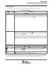
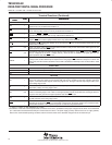
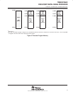
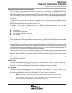
15 76543210
IPTR MP/MC OVLY AVIS DROM
CLK
OFF
SMUL SST
R/W R/W R/W R R R R/W R/W
LEGEND: R = Read, W = Write
Figure 2. Processor Mode Status (PMST) Registers
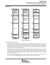
extended program memory
The ’5402 uses a paged extended memory scheme in program space to allow access of up to 1024K program
memory locations. In order to implement this scheme, the ’5402 includes several features that are also present
on the ’548/’549 devices:
D Twenty address lines, instead of sixteen
D An extra memory-mapped register, the XPC register, defines the page selection. This register is
memory-mapped into data space to address 001Eh. At a hardware reset, the XPC is initialized to 0.
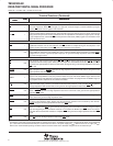
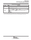
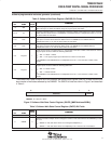
D Six extra instructions for addressing extended program space. These six instructions affect the XPC.
–
FB[D]
pmad (20 bits) – Far branch
–
FBACC[D]
Accu[19:0] – Far branch to the location specified by the value in accumulator A or
accumulator B
–
FCALL[D]
pmad (20 bits) – Far call
–
FCALA[D]
Accu[19:0]
– Far call to the location specified by the value in accumulator A or accumulator B
–
FRET[D]
– Far return
–
FRETE[D]
– Far return with interrupts enabled
D In addition to these new instructions, two ’54x instructions are extended to use 20 bits in the ’5402:
– READA data_memory
(using 20-bit accumulator address)
– WRITA data_memory
(using 20-bit accumulator address)
All other instructions, software interrupts and hardware interrupts do not modify the XPC register and access
only memory within the current page.
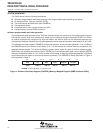
Program memory in the ’5402 is organized into 16 pages that are each 64K in length, as shown in Figure 3.