


TMS320VC5402
FIXEDĆPOINT DIGITAL SIGNAL PROCESSOR
SPRS079E – OCTOBER 1998 – REVISED AUGUST 2000
25
POST OFFICE BOX 1443 • HOUSTON, TEXAS 77251–1443
DMA channel index registers (continued)
The element index and the frame index affect address adjustment as follows:
D Element index: For all except the last transfer in the frame, the element index determines the amount to be
added to the DMA channel for the source/destination address register (DMSRCx/DMDSTx) as selected by
the SIND/DIND bits.
D Frame index: If the transfer is the last in a frame, the frame index is used for address adjustment as selected
by the SIND/DIND bits. This occurs in both single-frame and multi-frame transfer.
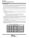
DMA interrupts
The ability of the DMA to interrupt the CPU based on the status of the data transfer is configurable and is
determined by the IMOD and DINM bits in the DMA channel mode control register (DMMCRn). The available
modes are shown in Table 6.
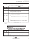
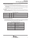
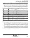
Table 6. DMA Interrupts
MODE DINM IMOD INTERRUPT
ABU (non-decrement) 1 0 At full buffer only
ABU (non-decrement) 1 1 At half buffer and full buffer
Multi-Frame 1 0 At block transfer complete (DMCTRn = DMSEFCn[7:0] = 0)
Multi-Frame 1 1 At end of frame and end of block (DMCTRn = 0)
Either 0 X No interrupt generated
Either 0 X No interrupt generated
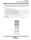
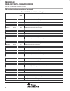
DMA controller synchronization events
The transfers associated with each DMA channel can be synchronized to one of several events. The DSYN bit
field of the DMA channel x sync select and frame count (DMSFCx) register selects the synchronization event
for a channel. The list of possible events and the DSYN values are shown in Table 7.
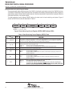
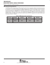
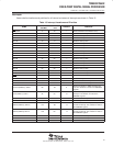
Table 7. DMA Synchronization Events
DSYN VALUE DMA SYNCHRONIZATION EVENT
0000b No synchronization used
0001b McBSP0 receive event
0010b McBSP0 transmit event
0011–0100b Reserved
0101b McBSP1 receive event
0110b McBSP1 transmit event
0111b–0110b Reserved
1101b Timer0 interrupt
1110b External interrupt 3
1111b Timer1 interrupt