


TMS320VC5402
FIXEDĆPOINT DIGITAL SIGNAL PROCESSOR
SPRS079E – OCTOBER 1998 – REVISED AUGUST 2000
32
POST OFFICE BOX 1443 • HOUSTON, TEXAS 77251–1443
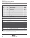
interrupts (continued)
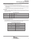
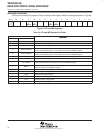
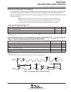
The bits of the interrupt flag register (IFR) and interrupt mask register (IMR) are arranged as shown in Figure 8.
15–14 13 12 11 10 9 8 7 6 5 4 3 2 1 0
RES DMAC5 DMAC4 BXINT1
or
DMAC3
BRINT1
or
DMAC2
HPINT INT3 TINT1
or
DMAC1
RES
or
DMAC0
BXINT0 BRINT0 TINT0 INT2 INT1 INT0
Figure 8. IFR and IMR Registers
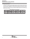
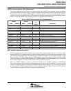
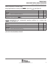
Table 14. IFR and IMR Register Bit Fields
BIT
FUNCTION
NUMBER NAME
FUNCTION
15–14 – Reserved for future expansion
13 DMAC5 DMA channel 5 interrupt flag/mask bit
12 DMAC4
DMA channel 4 interrupt flag/mask bit
11 BXINT1/DMAC3
This bit can be configured as either the McBSP1 transmit interrupt flag/mask bit, or the DMA
channel 3 interrupt flag/mask bit. The selection is made in the DMPREC register.
10 BRINT1/DMAC2
This bit can be configured as either the McBSP1 receive interrupt flag/mask bit, or the DMA
channel 2 interrupt flag/mask bit. The selection is made in the DMPREC register.
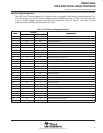
9 HPINT
Host to ’54x interrupt flag/mask
8 INT3
External interrupt 3 flag/mask
7 TINT1/DMAC1
This bit can be configured as either the timer1 interrupt flag/mask bit, or the DMA channel 1
interrupt flag/mask bit. The selection is made in the DMPREC register.
6 DMAC0
This bit can be configured as either reserved, or the DMA channel 0 interrupt flag/mask bit. The
selection is made in the DMPREC register.
5 BXINT0
McBSP0 transmit interrupt flag/mask bit
4 BRINT0
McBSP0 receive interrupt flag/mask bit
3 TINT0
Timer 0 interrupt flag/mask bit
2 INT2
External interrupt 2 flag/mask bit
1 INT1
External interrupt 1 flag/mask bit
0 INT0
External interrupt 0 flag/mask bit