Chapter 3: Standard Radar Operations 3-13
Measuring Range and
Bearing Using VRM/
EBLs
3.4 Measuring Range and Bearing Using VRM/EBLs
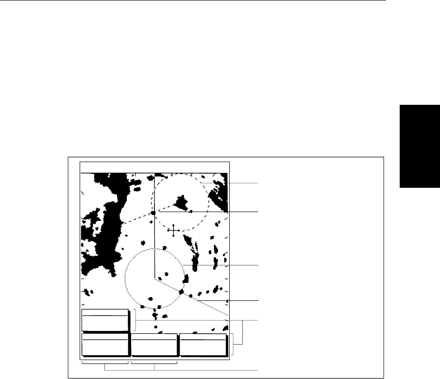
The Pathfinder Plus Radar display allows you to specify up to two Electronic
Bearing Lines (EBLs), each with an associated Variable Range Marker
(VRM), using the VRM/EBL key.
A standard VRM is displayed as a circle with its centre on your vessel’s
position, and it’s EBL is displayed as a line from the origin to the edge of the
radar picture display. However, each pair can be floated, so that the origin can
be moved.
Figure 3-11: EBL and VRM Displays
Note: When using VRM/EBLs, you may wish to turn off the range rings to
make the VRMs clearer (see Section 2.4).
VRMs move if you change the range scale, so that the actual range you have
marked is maintained. VRM/EBLs also move if you offset the centre.
When a VRM/EBL pair is active, its bearing and range are displayed in its
associated data box, which can be moved, deleted or reinstated.
The bearing information is displayed as either the bearing relative to your
vessel’s heading or (if heading data is available from a position fixer or
compass) the actual bearing in degrees magnetic or degrees true. These are
controlled by the setup parameters (see Section 7.4).
The VRM/EBL functions allow you to perform the following tasks:
T
AUTO
IR
015°
096
3nm
RR
OFF
VRM
VRM/EBL 2
TBRG
RNG nm
146°
1.70
CURSOR CURSOR
VRM/EBL 1
BRG
RNG nm
T
TBRG
RNG nm
50°47^72N
001°10^58N
H-UP
126°T
243°
0.98
D3974-1
Floated VRM2
(long-dashed line)
EBL1 (short-dashed line)
VRM/EBL data boxes
Two cursor readout boxes
Floated EBL2
(long-dashed line)
VRM1 (short-dashed line)
81186_3.book Page 13 Thursday, August 22, 2002 8:23 AM


