


69
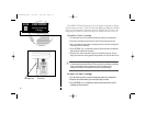
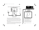
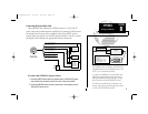
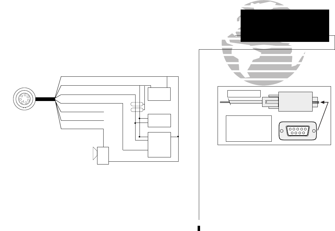
Connecting the power/data cable
The power/data cable connects the GPSMAP system to a 10-40 volt DC
power source and provides interface capabilities for connecting NMEA devices,
an external beacon receiver (if not equipped with built-in DGPS), and an
external alarm (see section 9 for interface operation details). The color code in
the diagram below indicates the appropriate harness connections.
To connect the GPSMAP to a power source:
1. Connect the RED harness lead to the positive side of a 10-40 volt DC power
source. Make sure the power lead has an in-line 2-amp fuse installed.
2. Connect the BLACK harness lead to a ground strip or the negative side of a
10-40 volt DC power source.
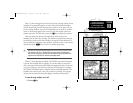
The GPSMAP system will interface to RS-232 devices
using NMEA data, to an external alarm device, and
to a PC (see PC connection info above).
To connect to an NMEA device, use the BLUE (out)
and BLACK (ground) harness leads. Some devices
will support bi-directional data exchange. For those
devices you must also use the BROWN (in) lead.
To connect an external alarm (100 mA max. coil
current), connect the ground side of the alarm device
or relay to the YELLOW harness lead.
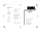
SECTION
B
APPENDIX
Wiring Installation
PIN 1 (red): 10-40 volts DC
PIN 2 (black): Ground
PIN 3 (blue): NMEA out
PIN 4 (brown): NMEA in
PIN 5 (white): no connect
PIN 6 (green): no connect
PIN 7 (yellow): alarm low
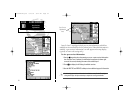
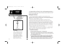
Connect the harness leads
from the GPS to a 9-pin serial
connector:
BLUE (Data Out) - Pin 2
BROWN (Data In) - Pin 3
BLACK (Ground) - Pin 5
PC Connections
DB-9
1
2
3
45
67
9
8
1
2
3
4
5
6
7
Pin assignment
(CABLE VIEW)
(-) (+)
10-40 volts DC
Autopilot/
NMEA Device
GBR 21/23
Beacon
Receiver
(for GPSMAP w/o
built-in DGPS)
Alarm/
Relay
(-)
Shield Grounded
Through GPS
(+)
(+)
(-)
(-)
OUT
IN
(+)
215225manb.qxd 4/27/00 9:22 AM Page 69