


provide ship’s L/L position data on their own
without other input requirements.
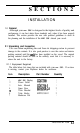
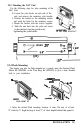
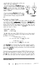
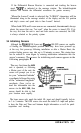
In a typical installation, the
6-pin
GPS sensor
connector is plugged directly into
the jack labeled
“GPS”
on the rear of the cabinet.
The 5
Pin plug
of the Loran-C sensor is connected to the jack
labeled “LORAN”.
‘SZ
zz
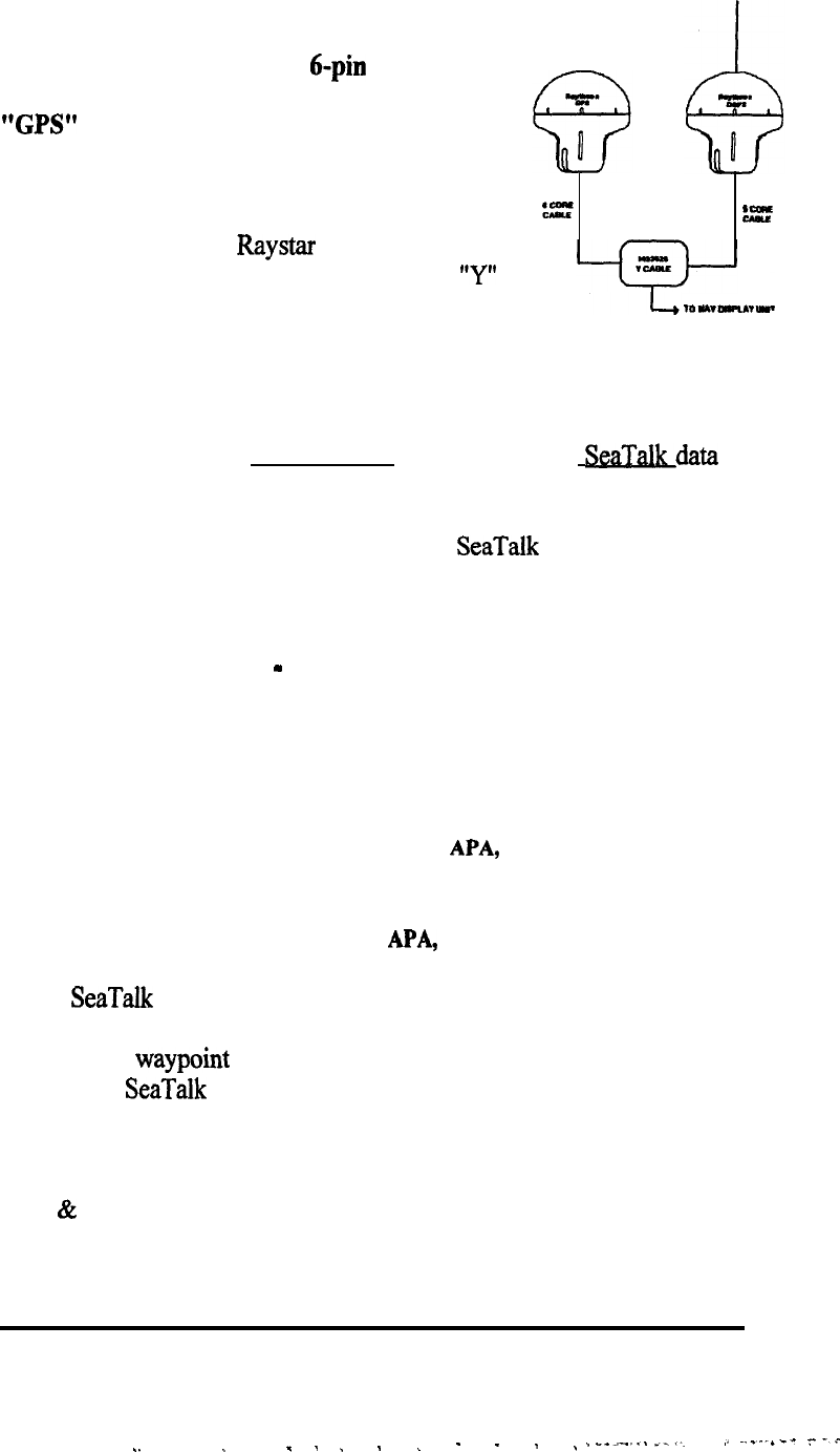
If you are using the
Raystar
108 GPS sensor
together with the DGPS Beacon Receiver, the
“Y”
cable lead marked “Display” plugs into the GPS
jack.
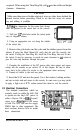
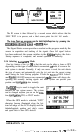
2.3.3 Interface to External Navaids
The Power cable assembly (shown in the figure) includes two wires which
can provide an output of NMEA 0183 formatted data or
SeaT&data
for
other navigational equipment such as radars, auto-pilots, video sounders, and
plotters. Since the NAV unit outputs one data or the other, the same
connections are used for either NMEA or
SeaTalk
data. The wires are
marked and colored as follows:
YELLOW = DATA+
GREEN
= DATA
-
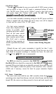
The NAV 398 may supply NMEA 0183 data for up to three external
equipments. Navaid devices connected to this output can receive the follow-
ing NMEA 0 183 sentences:
If LORAN Sensor is in use:
GLL, GTD, RMA, RMB, VTG,
APA,
APB, BWC.
If GPS Sensor is in use:
GLL, RMC, RMB, VTG,
APA,
APB, HSC, BWC.
When
SeaTalk
data is used, the NAV unit provides: magnetic variation,
COG, Cross-Track error, Lat./Long, GPS status data (including HDOP, fix
status), SOG,
waypoint
#, bearing, and distance, Arrival alarm, and MOB
signals to the SeaTalk bus.
External navigation equipment requiring NMEA 0183 data inputs nor-
mally obtain their required data via connection to the
NAV
398
data output (
yellow & green ) wires. However, some users may wish to operate the GPS
(or Loran) sensor unit directly with other navigational equipment capable of
INSTALLATION 2-6
.
.
_
_
.
_
_ _
-
.
.
,
~
___._...
_./
,I
---I-”
7.”