


required. When using the Trim Ring Kit, add
3/4”
to the width and height
clearance dimensions.
CAUTION
Make sure there are no hidden electrical wires or other items behind the
desired location before proceeding. Check to see that free access for mount-
ing and cabling is available.
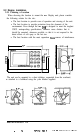
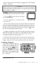
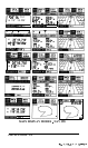
2.Using the dimensions for the cutout hole shown,
draw the pattern for the cutout hole on the console.
3. Drill two l/2” pilot holes inside the cutout guide
area at diagonal corners.
4. Using an appropriate saw, cut along the outside
of the cutout line.
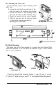
5. Remove the yoke knobs and the yoke and the rubber spacers from the
cabinet. If using the Flush Mount Kit verify that the unit fits correctly into
the cutout. If using the Trim Ring Kit, attach the Trim Ring, then test fit into
the cutout. It may be necessary to notch out some clearance in the cutout to
pass the trim ring hardware through the panel.
7. Complete the installation of the DC power cable, data output, and sensor
wiring into the console as per section 2.4 of this chapter. Be sure to allow
some slack in the cables for service to the equipment when necessary.
8. Connect all cables to the unit rear panel.
9. Insert the NAV unit into the panel. Use a flat washer, locking washer,
and nut on each stud and secure to the console. In some cases you may prefer
to apply a light coat of RTV sealant around the cutout to seal the console.
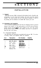
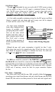
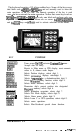
2.3 Electrical Connections
The standard connections which are
normally made to enable the
NAV 398
to operate are the ship’s DC power, to
either a Raynav 508 or 508A Loran-C
sensor or to a Raystar 108 GPS sensor
LO
or both. The NAV unit can also supply
NMEA data to other equipments. The
next sections discuss how to make NMEAj!EATALK
these connections.
INSTALLATION 2-4
_
._
,.
__
.
-
.
-.
_.j___-
_..,
.-
.-j
--,-