


Troubleshooting
LED Information
The Intel
®
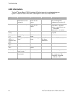
Server Board TIGI2U includes LEDs that can aid in troubleshooting your
system. A table of these LEDs with a description of their use is listed below.
LED Name Function Location Color Notes
ID Aid in server
identification from the
back panel
Control panel and
board rear left
corner
Blue Press ID LED button or user
Server Management
software to turn on the LED.
System fault Visible fault warning Control panel and
board rear left
corner
Green or Amber
Green = No Fault
Green Blink = degraded
Amber = critical error or non-
recoverable
Amber blink = non-critical
ATA drive
activity
Control panel Control panel Green Blinking = Activity. No action
required.
Memory fault
1–6
Identify failing memory
module
DIMM end rear of
board
Amber On = Fault
Diagnostic
LEDs. 1–4
(LSB, bit1, bit2,
MSB)
Displays port 80 POST
codes
Center back edge of
board
Each LED can be
Off, Green,
Amber, Red
See the POST code table
CPU 1 & 2 Fan
Fault
Identify fan failure Front center board Amber On = Fault
CPU 1 & 2
Fault
Identify processor failure 1” behind processor
socket
Amber On = Fault
5v Standby Identify 5v standby
power on state
Front left board Amber On = 5v standby power on
Power LED Identify the power state
of the system
Control Panel Green
Off = Power is off (off or S5)
On = Power on or S0)
Slow Blink = Low power
state (S1 – S3)
Intel
®
Carrier Grade Server TIGI2U User Guide
96