


Contents
Figures
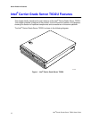
Figure 1. Intel
®
Carrier Grade Server TIGI2U ......................................................................16
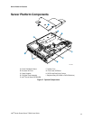
Figure 2. System Components.............................................................................................19
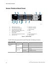
Figure 3. Platform Back........................................................................................................20
Figure 4. Front of Server Platform........................................................................................22
Figure 5. Optional Peripheral CD-ROM or DVD-ROM Drive................................................22
Figure 6. Intel
®
Server Platform TIGI2U Board Diagram......................................................23
Figure 7. Configuration Jumper Location.............................................................................24
Figure 8. SysCon Board.......................................................................................................26
Figure 9. System Cable Routing ..........................................................................................34
Figure 10. Removing the Chassis Cover .............................................................................35
Figure 11. Installing the Chassis Cover ...............................................................................36
Figure 12. Removing the Front Bezel ..................................................................................37
Figure 13. Installing the Front Bezel ....................................................................................38
Figure 14. Removing the Processor Air Duct.......................................................................39
Figure 15. Installing the Processor Air Duct.........................................................................40
Figure 16. Installing Memory DIMMs ...................................................................................41
Figure 17. Removing Heat Sink ............................................................................................43
Figure 18. Open the Processor Socket Lever.......................................................................44
Figure 19. Installing the Processor in the Processor Socket.................................................44
Figure 20. Close Processor Socket Lever.............................................................................45
Figure 21. Installing Heat Sink .............................................................................................45
Figure 22. Removing Hard Drive Carrier from Chassis........................................................46
Figure 23. Attaching a Hard Disk Drive to a Carrier.............................................................47
Figure 24. Inserting Hard Disk Drive Assembly into Chassis...............................................48
Figure 25. Removing CD-ROM / DVD-ROM Drive Assembly from Chassis........................49
Figure 26. Install CD-ROM Drive or DVD-ROM Drive Assembly into Chassis ....................50
Figure 27. Removing Riser Assembly from Chassis............................................................51
Figure 28. Installing Low-Profile PCI Card into Riser...........................................................52
Figure 29. Installing Full Length PCI Card into Riser...........................................................53
Figure 30. Removing a Low-Profile PCI Card......................................................................54
Figure 31. Removing a Full Height PCI Card.......................................................................54
Figure 32. Removing the Power Supply...............................................................................55
Figure 33. Installing the Power Supply.................................................................................56
Figure 34. DC Power In Male Connector Configuration.......................................................56
Figure 35. Connecting the Terminal Lug..............................................................................57
Figure 36. Removing the Four-Fan Assembly .....................................................................58
Figure 37. Installing the Four-Fan Assembly .......................................................................59
Figure 38. Removing the Mini Bezel ....................................................................................60
Figure 39. Removing the Front Panel Board........................................................................62
Figure 40. Replacing the Light Pipe.....................................................................................63
Figure 41. Inserting the Front Panel Board..........................................................................64
Figure 42. Cabling to Front Panel Board..............................................................................65
Figure 43. Removing the Low-Profile PCI Riser Board........................................................66
Figure 44. Removing the Full Height PCI Riser Board.........................................................67
Figure 45. Installing the Low-Profile PCI Riser Board..........................................................67
Figure 46. Installing the Full Height PCI Riser Board...........................................................68
Figure 47. Removing the Power Interface Board.................................................................69
Figure 48. Installing the Power Interface Board...................................................................70
Figure 49. Removing the Serial/Alarms Cable Threaded Standoffs ....................................71
Intel
®
Carrier Grade Server TIGI2U User Guide
13