


Platform Installations and Upgrades
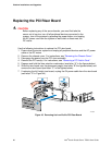
7. Disconnect the following cables on the Front Panel I/O Board:
Power interface board power from J1A1
CD-ROM / DVD-ROM data and power cables from the rear of the CD-ROM or
DVD-ROM drive
Front panel data from J5A1
HDD connector from J5A2
Front panel USB from J4B1
System fan control connector from J7A1
Fan connectors from J7A2, J8A1, J8A2 and J9A1
Telco Alarms cable from J9A2
SCSI channel from J5B1
SCSI flex 1 from J9D1
SCSI flex 2 from J5C1
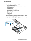
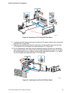
8. Remove the screws near the blind-mate connector (J2A1) and the fan assembly
connector (J7A1).
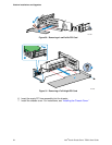
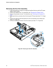
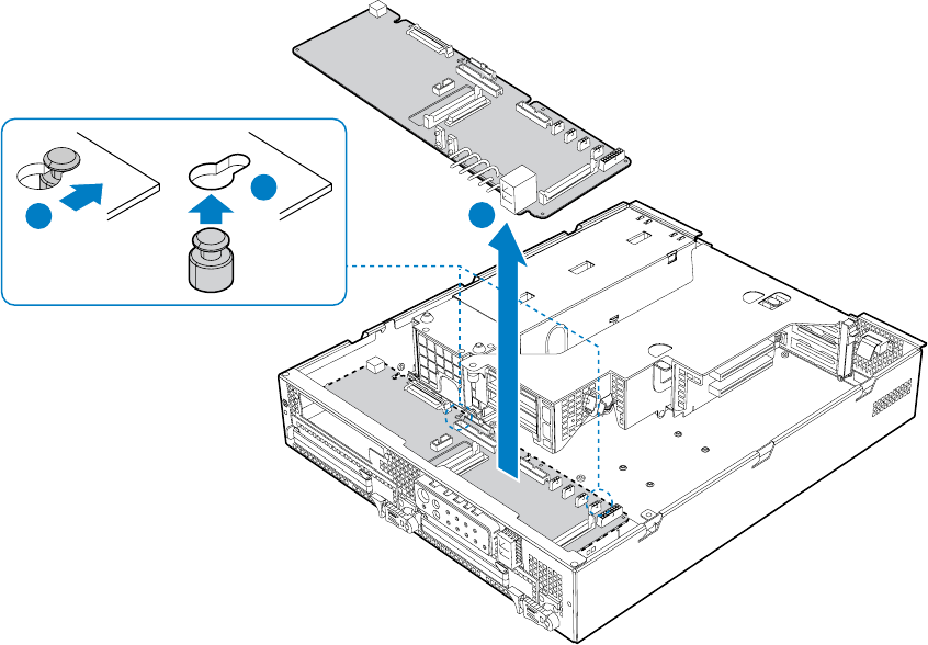
9. Gently work the front panel I/O board backward (see letter “A” in
Figure 39), toward the
rear of the chassis to disengage the light pipe from behind the front mini-bezel.
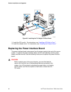
10. Pull the front panel I/O board up over the placement pegs (see letter “B” in
Figure 39)
and lift it from the chassis (see letter “C” in
Figure 39).
TP01655
C
B
A
Figure 39. Removing the Front Panel Board
Intel
®
Carrier Grade Server TIGI2U User Guide
62