


Server Platform Features
Front Panel IO (FPIO) System Board
Features
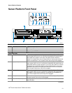
The TIGI2U server system has the following FPIO features:
• Four switches to control power-on, reset, NMI, and the system ID LED
• One system ID LED that can be controlled remotely or by the system ID switch
• Two system activity LEDs that indicate power-on and NIC activity
• Two hard drive activity/fault LEDS that indicate activity/fault status for drives 1 and 2
• Four system fault LEDs that indicate critical, major, minor, and power system fault
status
• Four system fault relays for external critical, major, minor, and power fault indicators
• One SCSI bus with hot-swap circuitry for controlling hot-swap SCSI disk drives 1 and 2
• IDE Bus from IDE Connector to blind mate connector
• One blind mate connector for interfacing to CDROM or floppy drive carrier assembly
• Connectors for interfacing to the power supply, server baseboard, drive carrier
assemblies, and hot plug disk drives 1 and 2
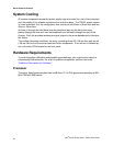
FPIO SCSI Subsystem Status LEDs
The status LEDs give the user a visual indication of the drives’ condition. There is a single
LED for each drive. The LEDs are bi-colored and use a combination of color and blinking
frequency to indicate multiple conditions. The LEDs are mounted on the FPIO board, and
the light is directed to the front panel through the use of a light pipe assembly. See
Table
4
for LED activity definitions. See the Firmware EPS for definitions of the different blink
rates.
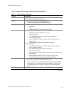
Table 4. LED Activity Definitions
LED State Drive Active Fault Condition
Solid Green
Blinking Green X
Blinking
Yellow/Green
X
Blinking
Yellow/Blank
X
Blank
Intel
®
Carrier Grade Server TIGI2U User Guide
25