


Platform Installations and Upgrades
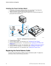
Installing the Front Panel I/O Board
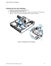
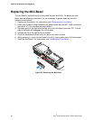
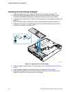
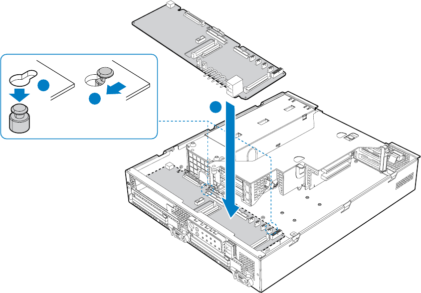
1. Lower the replacement Front Panel I/O Board into the chassis (see letter “A”).
2. While holding the rear edge of the board, ease the board forward, sliding the NIC
connector and USB port through the matching cutout at the front of the chassis.
3. Lower the rear of the board into position fitting the board over the placement pegs (see
letter “B”).
4. Push the board forward, locking the board onto the placement pegs (see letter “C”).
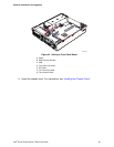
5. Replace the screws you removed previously, near the blind-mate connector (J2A1)
and the fan assembly connector (J7A1).
TP01700
C
B
A
Figure 41. Inserting the Front Panel Board
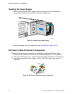
6. Install the power interface board. For instructions, see “Installing the Power Interface
Board
.”
7. Install the power supply. For instructions, see “
Installing the Power Supply.”
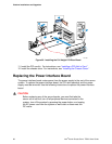
8. Reconnect all cables to the Front Panel I/O Board. Note that most connectors are
labeled to match the connection point on the boards.
Intel
®
Carrier Grade Server TIGI2U User Guide
64