


Garmin aera 500 Series Pilot’s Guide
190-01117-02 Rev. A
95
Hazard Avoidance
Overview GPS Navigation Flight Planning Hazard Avoidance Additional Features Appendices Index
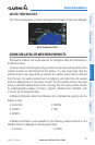
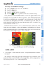
Terrain and obstacle databases are referenced to MSL. Using the GPS position
and altitude, the Terrain feature portrays a 2-D picture of the surrounding terrain and
obstacles relative to the position and altitude of the aircraft. GPS position and GPS-
MSL altitude are used to calculate and predict the aircraft’s flight path in relation to the
surrounding terrain and obstacles. In this way, the pilot can view predicted dangerous
terrain and obstacle conditions.
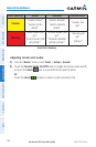
Alert windows appear to inform the pilot of proximity to the terrain and obstacles,
as well as an unsafe descent rate. These alerts depend on user-defined parameters in
the Terrain Setup.
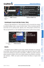
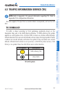
TERRAIN INFORMATION
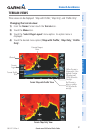
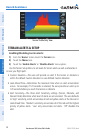
Two views are displayed by the Terrain function: the Map View, and the Profile View.
The areas of the terrain shaded red are predicted to be within 100 feet below or
above the aircraft. The yellow terrain areas are between the user-defined Caution
Elevation and 100 feet below the aircraft. By default, the Caution Elevation is 1,000
feet; therefore, the areas in yellow are between 1,000 feet and 100 feet below the
aircraft. The black areas are further than the Caution Elevation. A projected point of
impact is marked with an “X” symbol.
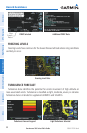
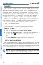
OBSTACLE INFORMATION
Obstacles are shown on the Terrain Map View, at or below the map range of 12 nm.
Obstacles are also shown on the Navigation Map when the map range is set to 5 nm
or below.
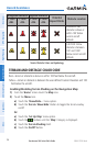
Standard aeronautical chart symbols are used for lighted or unlighted obstacles
taller than 200 feet Above Ground Level (AGL). Refer to the Obstacle Icons legend
below.
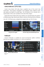
When selecting an obstacle with the Map Pointer, each obstacle displays the altitude
at the top of the obstacle, or Mean Sea Level (MSL). Each obstacle also lists the actual
height of the obstacle, or Above Ground Level (AGL).