Reference Manual
00809-0100-4811, Rev CA
February 2006
6-13
Rosemount 3300 Series
Amplitude Threshold
Settings
The amplitude thresholds are automatically adjusted to appropriate values in
order to filter out noise and other non-valid measurements from the
measurement signal.
The amplitude of the measurement signal, i.e. the amplitude of the signal that
is reflected by the product surface, is related to the actual dielectric constant
of the product. The amplitude threshold that is used by the transmitter is
based on the parameter configuration of the current product dielectric
constant (see Section 4: Basic Configuration). Normally no other threshold
adjustment is needed, but if the transmitter still does not track the product
surface correctly it may be necessary to adjust the threshold values.
The Radar Configuration Tool (RCT) has a plot function allowing you to view
the reflections along the probe.
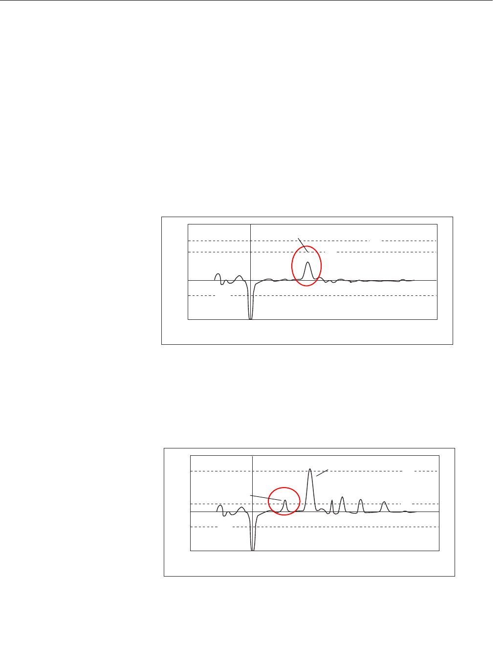
If the amplitude threshold is too high the product level is not detected as
illustrated in Figure 6-10.
Figure 6-10. Example 1:
amplitude threshold T2 is too
high.
If there are disturbing objects in the tank the threshold must be carefully set in
order to avoid locking on the wrong amplitude peak. In Figure 6-11 the
transmitter has locked on a peak above the actual product surface, i.e. a
disturbance was interpreted as the product surface, whereas the actual
product surface was interpreted as an interface or the probe end.
Figure 6-11. Example 2:
amplitude threshold T2 is too
low.
P1
T1
T2
T3
Amplitude
Distance (samples)
100
80
60
-60
40
-40
20
-20
0
0 100 200 300 400 500 600
100
50
0
150
200
250
T2 is above the
Level peak
WAVEFORMPLOT THRESHOLD HIGH
P1
P2
P3
T1
T2
T3
Amplitude
Distance (samples)
100
80
60
-60
40
-40
20
-20
0
0 100 200 300 400 500 600
100
50
0
150
200
250
Actual surface
Disturbing echo
misinterpreted as
product surface
WAVEFORMPLOT THRESHOLD LOW


