


Reference Manual
00809-0100-4811, Rev CA
February 2006
2-7
Rosemount 3300 Series
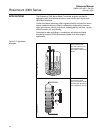
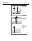
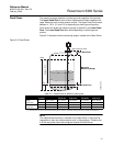
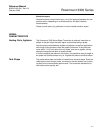
Dead Zones The measuring range depends on probe type and properties of the product.
The Upper Dead Zone is the minimum measurement distance between the
upper reference point and the product surface. The Upper Dead Zone varies
between 4 - 20 in. (0.1 and 0.5 m) depending on probe type and product.
At the end of the probe the measuring range is reduced by the Lower Dead
Zone. The Lower Dead Zone also varies depending on probe type and
product.
Figure 2-5 illustrates how the measuring range is related to the Dead Zones:
Figure 2-5. Dead Zones
NOTE
The measurement accuracy is reduced in the Dead Zones. It may even be
impossible to make any measurements at all in those regions. Therefore the
4-20 mA set points should be configured outside the Dead Zones.
4mA
20mA
Upper Dead Zone
Lower Dead Zone
Range 0 -100 %
Maximum
Measuring Range
Upper Reference Point
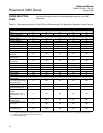
DEAD ZONES
Table 2-2. Dead Zones for different probe types
Dielectric
Constant
Coaxial Probe Rigid Twin
Lead Probe
Flexible Twin
Lead Probe
Rigid Single
Lead Probe
Flexible Single
Lead Probe
Upper
Dead Zone
2 4 in. (10 cm) 4 in. (10 cm) 8 in. (20 cm) 4 in. (10 cm) 20 in. (50 cm)
80 4 in. (10 cm) 4 in. (10 cm) 5.9 in. (15 cm) 4 in. (10 cm) 5.9 in. (15 cm)
Lower
Dead Zone
2 2 in. (5 cm) 2.8 in. (7 cm) 5.9 in. (15 cm) 4 in. (10 cm)
(1)
4.7 in. (12 cm)
80 1.2 in. (3 cm) 2 in. (5 cm) 2 in. (5 cm) 2 in. (5 cm) 2 in. (5 cm)
(1) Dead Zone=8 inch (20 cm) when SST centering disc is mounted. The PTFE centering disc does not affect the Dead Zone.