


Reference Manual
00809-0100-4811, Rev CA
February 2006
3-7
Rosemount 3300 Series
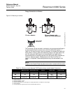
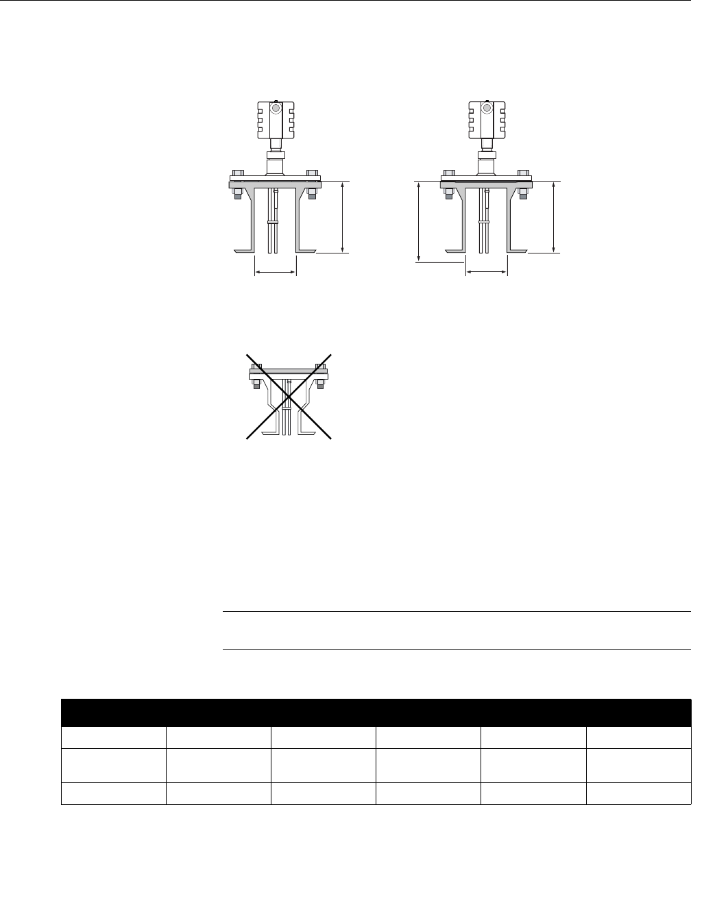
Flange Connection on Nozzles
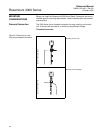
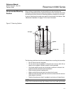
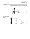
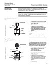
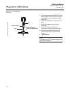
Figure 3-3. Mounting in nozzles
The transmitter can be mounted in nozzles by using an appropriate flange. It
is recommended that the nozzle size is within the dimensions given in
Table 3-4. For small nozzles it may be necessary to increase the Upper Null
Zone (UNZ) in order to reduce the measuring range in the upper part of the
tank. By setting the UNZ equal to the nozzle height, the impact on the
measurement due to interfering echoes from the nozzle will be reduced to a
minimum. See also section “Disturbances at the Top of the Tank“ on
page 6-11. Amplitude Threshold adjustments may also be needed in this
case.
NOTE
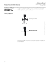
Except for the Coaxial Probe the probe must not be in contact with the nozzle.
H
D2=min. diameter with
Upper Null Zone adjustment
HUNZ
NO_REDUCER/NOZZLE MOUNT V3
Avoid nozzles
with reducer
D1=min. diameter
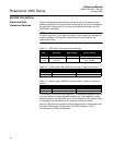
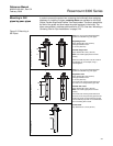
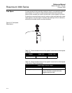
Table 3-4. Minimum nozzle diameter D1/D2 and maximum nozzle height H (inch/mm).
Rigid Twin Lead Flexible Twin Lead Coaxial Single Lead Flexible Single
D1
(1)
4/100 4/100 > Probe diameter 6/150 6/150
D2
(2)
2/50 2/50 > Probe diameter 2/50
(3)
1.5/38
(4)
2/50
H
(5)
4/100 + D
(6)
4/100 + D
(6)
- 4/100 + D
(6)
4/100 + D
(6) (7)
(1) Upper Null Zone=0.
(2) Upper Null Zone>0.
(3) Process connection 1.5 inch.
(4) Process connection 1 inch.
(5) Recommended maximum nozzle height. For coaxial probes there is no limitation on nozzle height.
(6) Nozzle diameter.
(7) For tall nozzles the Long Stud version is recommended (option code LS).