


Reference Manual
00809-0100-4811, Rev CA
February 2006
Rosemount 3300 Series
3-4
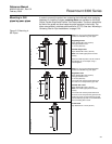
BEFORE YOU INSTALL
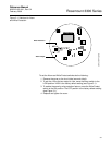
Alarm and Write
Protection Switches
Electronic boards are electrostatically sensitive. Failure to observe proper
handling precautions for static-sensitive components can result in damage to
the electronic components. Do not remove the electronic boards from the
3300 Radar Transmitter.
NOTE
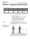
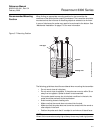
To ensure long life for your radar transmitter, and to comply with hazardous
location installation requirements, tighten covers on both sides of the
electronics housing.
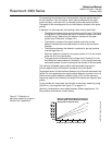
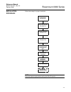
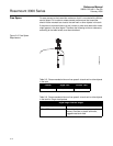
The transmitter monitors its own operation. This automatic diagnostic routine
is a timed series of checks repeated continuously. If the diagnostic routine
detects a failure in the transmitter, the 4–20 mA output is driven upscale (high)
or downscale (low) depending on the position of the Alarm switch.
Security write protection prevents unauthorized access to configuration data
through the Rosemount Configuration Tool (RCT) software, a Field
Communicator or AMS Suite software.
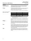
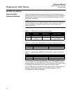
Table 3-1. 3300 Radar Transmitter Switch Settings
Switch
Bank
Description Default Setting Position Settings
Alarm 4–20 mA Alarm Output High High, Low
Write
Protect
Security Write
Protection
Disabled (OFF) ON = Enabled,
OFF = Disabled
Table 3-2. Analog Output: Standard Alarm Values vs. Saturation Values
Level 4–20 mA Saturation Values 4–20 mA Alarm Value
Low 3.9 mA 3.75 mA
High 20.8 mA 21.75 mA
Table 3-3. Analog Output: NAMUR-Compliant Alarm Values vs. Saturation
Values
Level 4–20 mA Saturation Values 4–20 mA Alarm Value
Low 3.8 mA 3.6 mA
High 20.5 mA 22.5 mA