


Reference Manual
00809-0100-4811, Rev CA
February 2006
Rosemount 3300 Series
4-2
CONFIGURATION
PARAMETERS
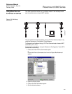
The Rosemount 3301 transmitter can be configured for level and volume
measurements. The Rosemount 3302 is designed to measure interface level
and interface distance as well.
The 3300 transmitter can be pre-configured according to the ordering
specifications in the Configuration Data Sheet.
Basic Configuration The basic transmitter configuration includes setting the tank geometry
parameters. For interface measurements the dielectric constant of the top
liquid must also be given. For some applications with heavy vapor, the vapor
dielectric must be given as well.
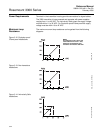
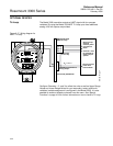
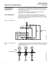
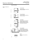
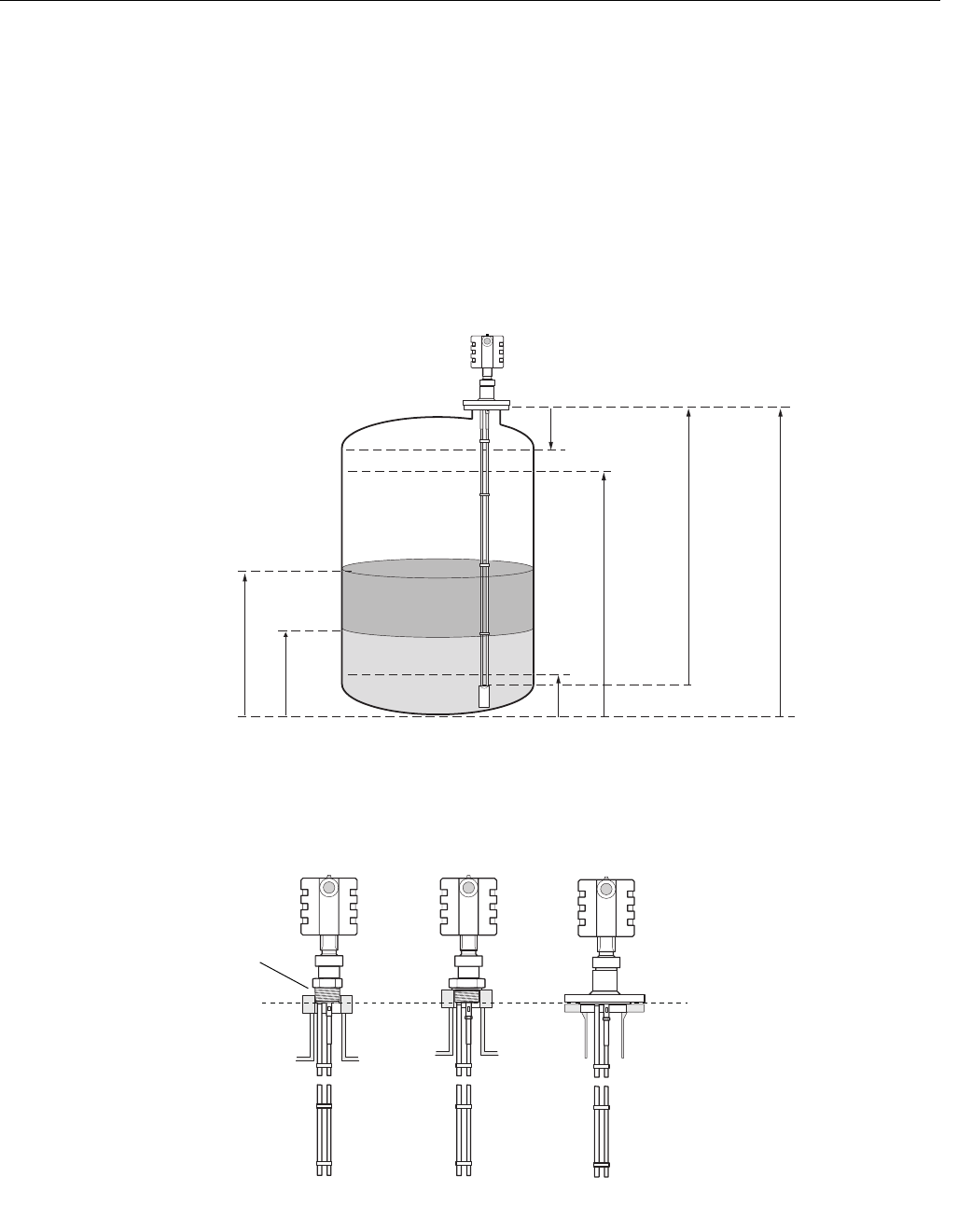
Figure 4-1. Tank Geometry
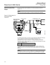
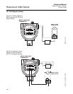
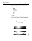
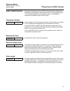
Figure 4-2. Upper Reference
Point
For the different tank connections the Upper Reference Point is located at the
underside of the threaded adapter or at the underside of the welded flange, as
illustrated in Figure 4-2:
4mA
20mA
Reference Gauge
Height
Upper Null Zone
Product Level
Upper Reference Point
Lower Reference Point
Interface
Level
Probe
Length
TANK GEOMETRY
NPT BSP (G) FLANGE
Upper Reference Point
3300_UPPERREFERENCE_BA.EPS
Adapter