


Reference Manual
00809-0100-4811, Rev CA
February 2006
Rosemount 3300 Series
4-20
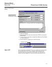
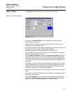
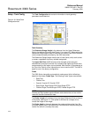
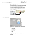
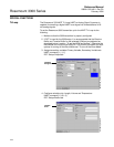
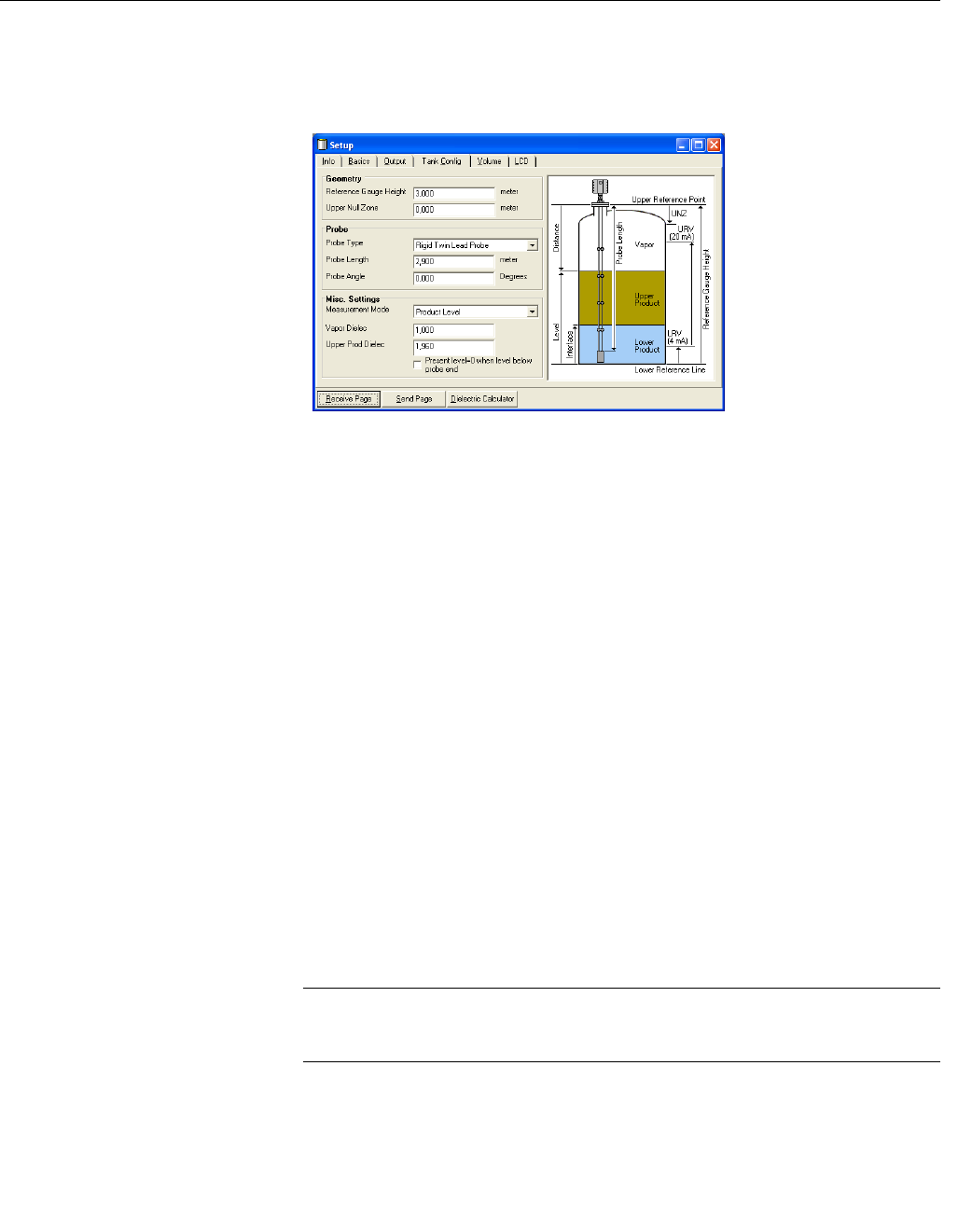
Setup - Tank Config The Tank Configuration tab contains information on tank geometry
parameters and dielectrics.
Figure 4-16. Setup Tank
Configuration tab
Tank Geometry
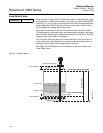
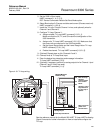
The Reference Gauge Height is the distance from the Upper Reference
Point to the bottom of the tank (see Figure 4-1 on page 4-2). When setting the
Reference Gauge Height, keep in mind that this value is used for all level and
volume measurements performed by the 3300 transmitter.
The Reference Gauge Height must be set in linear (level) units, such as feet
or meters, regardless of primary variable assignment.
The Upper Null Zone (UNZ) should not be changed unless there are
disturbances at the top of the tank. By increasing the Upper Null Zone value
measurements in this region can be avoided. See Section 6: Disturbances at
the Top of the Tank for more information on how to use the UNZ. The UNZ is
equal to zero in the factory configuration.
Probe
The 3300 Series transmitter automatically makes some initial calibrations
based on the chosen Probe Type. The following Probe Types are available:
• Rigid Twin
• Flexible Twin
• Coaxial, Coaxial HP, Coaxial HTHP
• Rigid Single, Rigid Single HTHP, Rigid Single PTFE
• Flexible Single, Flexible Single HTHP, Flexible Single PTFE
NOTE
Flexible and Rigid probes require different radar electronics and can not be
used with the same transmitter head
The Probe Length is the distance from the Upper Reference Point to the end
of the probe, see Figure 4-1. If the probe is anchored to a weight do not
include the height of the weight.
The Probe Angle is the angle between the probe and the vertical line. Set
this value equal to zero if the transmitter is mounted with the probe along the
vertical line (which is normally the case).
RCT-SETUP_TANKCONF_V2.TIF