


Reference Manual
00809-0100-4811, Rev CA
February 2006
Rosemount 3300 Series
3-24
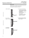
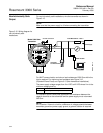
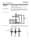
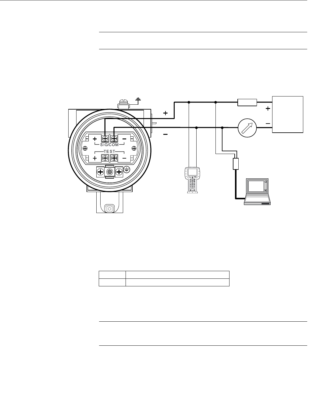
Non-Intrinsically Safe
Output
For non-intrinsically safe installations, wire the transmitter as shown in
Figure 3-15.
NOTE!
Make sure that the power supply is off when connecting the transmitter.
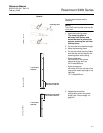
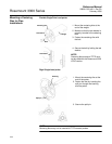
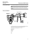
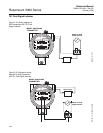
Figure 3-15. Wiring diagram for
non-intrinsically safe
installations.
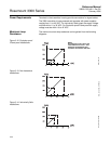
For HART communication a minimum load resistance of 250 Ohm within the
loop is required. For maximum load resistance see Figure 3-12
(Explosion/Flame Proof) and Figure 3-13 (Non-hazardous installations).
The power supply voltage ranges from V
min
VDC to 42 VDC where V
min
is the
minimum voltage given by:
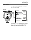
For Explosion-proof/Flame-proof applications the resistance between the
negative terminal on the transmitter and the power supply must not exceed
300 Ohm.
NOTE!
EEx d version: If there is a risk for a difference in voltage potential between
transmitter ground an power supply ground, a galvanic isolator is required.
Load Resistance = 250 Ω
Power Supply
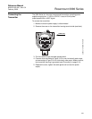
375 Field
Communicator
Model 3300 Radar
Transmitter
HART modem
PC
WIRING NON IS
V
min
- 42 VDC
Ground Connection
11 V Non-hazardous locations certification
16 V Explosion-proof/flame-proof certification