Reference Manual
00809-0100-4811, Rev CA
February 2006
Rosemount 3300 Series
3-26
OPTIONAL DEVICES
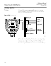
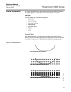
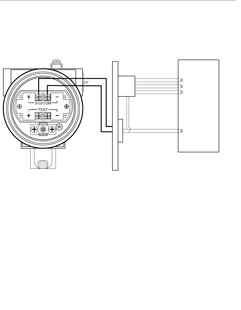
Tri-Loop The Model 3300 transmitter outputs a HART signal with four process
variables. By using the Model 333 HART Tri-Loop up to three additional
analog 4-20 mA outputs are provided.
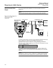
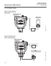
Figure 3-17. Wiring diagram for
HART Tri-Loop
Configure Channels 1, 2, and 3 to reflect the units as well as Upper Range
Values and Lower Range Values for your secondary, tertiary and fourth
variables (variable assignment is configured in the Model 3300). It is also
possible to enable or disable a channel from this menu. See “Special
Functions“ on page 4-24 for further information on how to install a Tri-Loop.
Ch. 3
Ch. 2
Ch. 1
Each Tri-Loop
Channel
recieves power
from Control
Room
Channel 1 must
be powered for
the Tri-Loop to
operate
Device recieves
power from
Control Room
R
L
≥ 250 Ω
HART Burst Command 3/
Analog Output
Intrinsically Safe Barrier
DIN Rail Mounted
HART Tri-Loop
Control Room
WIRING TRILOOP
Burst Input
to Tri-Loop


