


Reference Manual
00809-0100-4811, Rev CA
February 2006
Rosemount 3300 Series
www.rosemount.com
Section 5 Operating the Display Panel
Display Functionality . . . . . . . . . . . . . . . . . . . . . . . . . . . . . page 5-1
Error Messages . . . . . . . . . . . . . . . . . . . . . . . . . . . . . . . . . . page 5-2
DISPLAY
FUNCTIONALITY
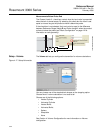
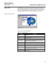
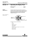
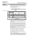
The Rosemount 3300 transmitter uses the display for presentation of
measurement variables. The display has two rows, the upper row with five
characters is for the measured value and the lower row with six characters for
the value name and measurement unit. The display toggles between the
different variables every 2 seconds. Variables to be presented are
configurable by using a Field Communicator or by using the Radar
Configuration Tools software.
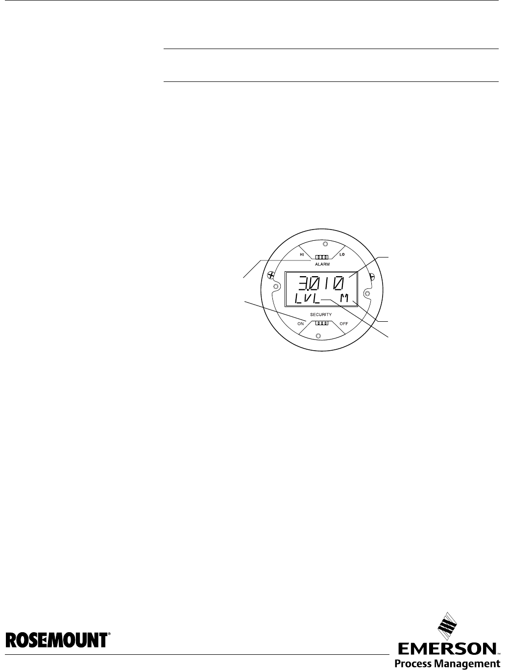
Figure 5-1. Presentation of
measurement data
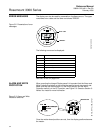
Model 3300 can display the following variables:
•Level
• Distance
•Volume
• Internal Temperature
• Interface Distance
• Interface Level
• Amplitude 1, 2 and 3 (see chapter 6 for more information)
• Interface Thickness
• Percent of range
• Analog current out
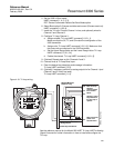
Measurement value
Measurement unit
DISPLAY1
Measurement variable
Jumpers for Alarm
and Write
Protection settings