


Reference Manual
00809-0100-4811, Rev CA
February 2006
6-3
Rosemount 3300 Series
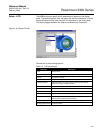
Plotting the
Measurement Signal
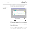
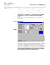
The Radar Configuration Tool (RCT) has powerful tools for advanced
troubleshooting. By using the Waveform Plot function you get an instant view
of the tank signal. Measurement problems can be solved by studying the
position and amplitude of the different pulses.
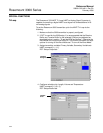
To plot the measurement signal:
1. Start the Radar Configuration Tool program.
2. Choose the View>Plotting menu option, or choose the Plotting icon in
the RCT workspace (Advanced page at the left side of the workspace)
and click the Read button.
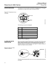
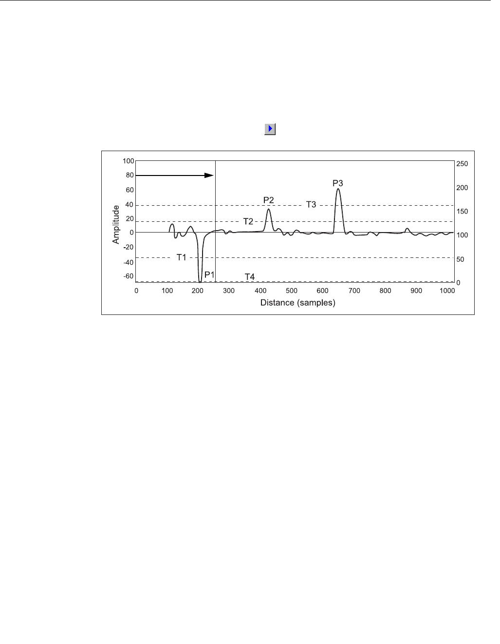
Figure 6-2. Waveform plot in RCT
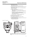
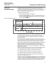
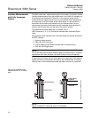
In a typical measurement situation the following pulses appear in the diagram:
P1 - Reference pulse. This pulse is caused by the transition between
transmitter head and probe. It is used by the transmitter as a reference at
level measurements.
P2 - Product surface. This pulse is caused by a reflection on the product
surface. In Measurement Mode=Interface when Immersed Probe however, P2
indicates the interface since the surface of the upper product is ignored.
P3 - Interface or probe end. This pulse is caused by reflection on the interface
between an upper product and a bottom product with a relatively high
dielectric constant. It may also be caused by the probe end if there is no
product above. This pulse is shown when the transmitter is in Measurement
Mode=Level & Interface.
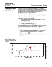
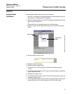
Different amplitude thresholds are used in order to filter out unwanted signals.
The following amplitude thresholds are used for the 3300 transmitter:
T1 - amplitude threshold for detection of the Reference pulse P1.
T2 - amplitude threshold for detection of the product level peak P2.
T3 - amplitude threshold for detection of the interface level peak P3.
T4 - amplitude threshold that is used to detect whether the probe is fully
immersed in the upper product or not.
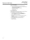
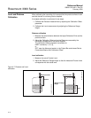
Normally the thresholds are adjusted to approximately 50% of the signal peak
amplitude. To adjust the Amplitude Thresholds open the Advanced section
in the RCT Project Bar and choose Device Commands>Details>Set Nominal
Thresholds. To reset the default values set Amplitude Threshold=0 (zero).
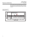
Upper Null Zone
WAVEFORMPLOT_GENERAL