


Reference Manual
00809-0100-4811, Rev CA
February 2006
3-25
Rosemount 3300 Series
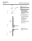
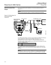
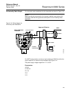
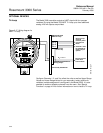
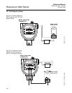
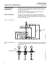
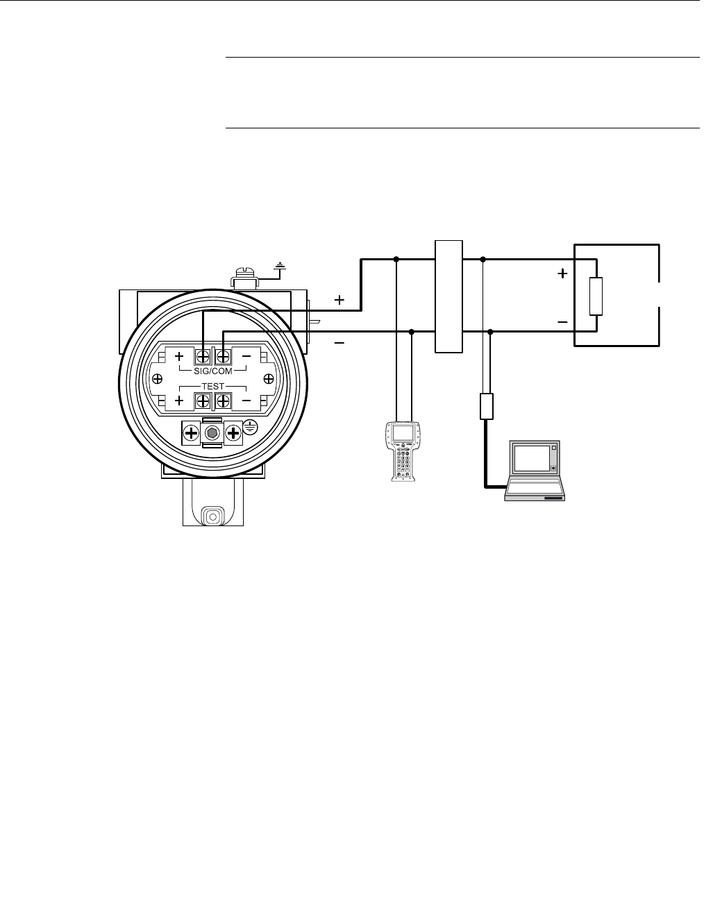
Intrinsically Safe Output For intrinsically safe installations wire the transmitter as shown in Figure 3-16.
NOTE!
Make sure that the instruments in the loop are installed in accordance with
intrinsically safe field wiring practices and System Control Drawings when
applicable.
Figure 3-16. Wiring diagram for
intrinsically safe installations
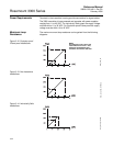
For HART communication a minimum load resistance of 250 Ohm within the
loop is required. For maximum load resistance see Figure 3-14.
The power supply voltage ranges from 11 V to 30 V.
IS parameters
Ui=30 V.
Ii=130 mA.
Pi=1 W.
Ci=0.
Li=0.
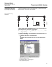
DCS
R
L
=250 Ω
Approved IS barrier
375 Field
Communicator
HART modem
PC
Power Supply
Model 3300 Radar
Transmitter
WIRING IS
11 - 30 VDC
Ground Connection