


• Reference Waveform
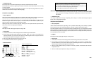
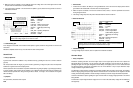
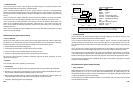
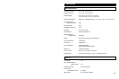
VEHICLE INFORMATIONS
YEAR
:
1993
MAKE : Ford
MODEL : F150 4WD Pickup
ENGINE : 5.0 L
FUELSYS : Multiport Fuel Injection
PCM_PIN : CH A 56 GryOrg wire
CH B 36 Pnk wire
STATUS : KOER (Key On Running)
RPM : 3000
ENG_TMP : Operating Temperature
VACUUM : 21 In. Hg
MILEAGE : 66748
• Troubleshooting Tips
If changing manifold vacuum has no effect on the rising edges of SPOUT, check for a faulty BP/MAP sensor.
If PIP is absent, the engine will not start; check for a bad TFI module or other distributor problem.
If
S
POUT is
absen
t
, the
system may
be in LOS (Limited Opera
t
ion Strategy) or limp-home mode. Check for
problems in the PCM or bad wiring harness connectors.
If the rising edges of PIP or SPOUT are rounded, timing will be inaccurate, although the system may not set an error
code. Check for problems in the module producing each signal.
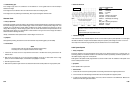
DI (Distributor Ignition) Primary
• Theory of Operation
The ignition coil primary signal is one of the top three most important diagnostic signals in powertrain management
systems. This signal can be used for diagnosing the driveability problems such as no starts, stalls at idle or while
driving, misfires, hesitation, cuts out while driving, etc.
The waveform displayed
from the ignition primary circuit is very useful because occurrencies in
t
he ignition
secondary burn are induced back into the primary through mutual induction of the primary and secondary windings.
This test can provide valuable information about the quality of combustion in each individual cylinder. The waveform
is primarily used to :
1. analyze individual cylinder’s dwell (coil charging time),
2. analyze the relationship between ignition coil and secondary circuit performance (from the firing line or ignition
voltage line),
3. locate incorrect air-fuel ratio in individual cylinder (from the burn line), and
6-59
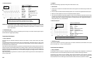
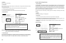
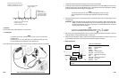
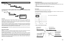
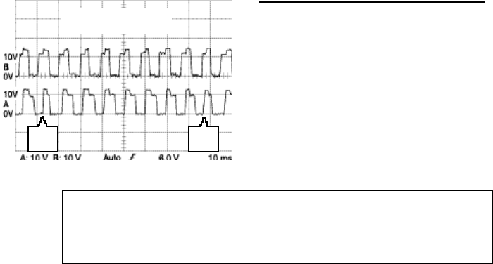
The edges must be sharp. Anything tha
t
affects ignition timing should change the
position of SPOUT (upper trace) with respect to PIP (lower trace). The notches out o
f
the
top and bo
t
tom corner of PIP go away when the SPOUT connector is removed because
this cuts of
f
the
TFI’s ability to encode the PIP signal with the SPOUT in
f
ormation.
Ford EEC-IV PIP and SPOUT
signals logged at 3000 RPM
“sync”
pulse
“sync”
pulse
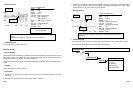
PIP (Profile Ignition Pickup)/SPOUT (Spark Output)
•
Theory of Operation
The most common electronic ignition system found on Ford vehicles (primarily on Ford/Lincoln/Mercury) has been
dubbed TFI for Thick Film Ignition. This system uses a Hall Switch in the TFI module, mounted on the distributor, to
produce a basic spark timing signal, PIP (Profile Ignition Pickup). This signal is sent to the PCM and the PCM uses
t
his signal
to monitor results and accurately time the fuel injector and electronic spark timing output
(SPOUT)
signals. The PCM sends the SPOUT back to the TFI module, which then fires the ignition coil primary circuit. The
PIP signal is primarily a frequency modulated signal that increases and decreases its frequency with engine RPM,
but it has also a pulse width modulated componen
t
bec ause i
t
is ac
t
ed upon by
the TFI module, based on
information previously received via the SPOUT signal.
The SPOUT signal is a pulse width modulated signal because the PCM continually alters the SPOUT signal’s pulse
width, which has the primary ignition dwell and ignition timing advance information encoded in it. The frequency of
the SPOUT signal also increases and decreases with engine RPM because it simply mimics the frequency of the
PIP signal.
Many GM/European/Asian vehicles use a similar overall ignition circuit design.
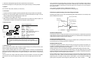
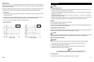
The rising and falling edges of the SPOUT move in relation to PIP. The rising edge controls spark timing and the
falling edge controls coil saturation (dwell).
Watching
both
simul
t
aneously using this instrumen
t
will
t
ell you whether the PCM can
compute timing based on
sensor inputs. For example, if the MAP sensor fails, the rising edge of SPOUT will not move relative to the rising
edges of PIP when Manifold Absolute Pressure changes.
• Symptoms
Engine stall out, misfire, slow advance timing, hesitations, no start, poor fuel economy, low power, high emissions
• Test Procedure
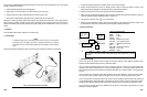
1. Connect the ground leads of both channel test leads to the chassis GND’s. Connect the CH A to the PIP signal
and the CH B to the
S
POUT signal. Use a wiring diagram for the vehicle being serviced
to get the
PCM pin
number, or color of the wire for each circuit.
2. Crank or start the engine.
3. With the Key On, Engine Running (KOER), let the engine idle, or use the throttle to accelerate and decelerate the
engine, or drive the vehicle as needed to make the driveability problem occur.
4. Look closely to see that the frequency of both signals is keeping pace with engine RPM and that the pulse width
on the pulse width modulated notches of the signal changes when timing changes are required.
5. Look for abnormalities observed in the waveforms to coincide with an engine sputter or driveability problem.
6-58