


•
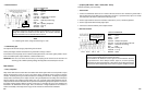
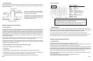
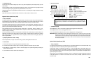
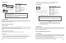
Reference Waveform
VEHICLE INFORMATION
YEAR : 1988
MAKE : Nissan/Datsun
MODEL : 300 zx non-turbo
ENGINE : 3.0 L
FUELSYS : Multiport Fuel Injection
PCM_PIN
:
12 Wht wire at the instrument cluster
STATUS : KOBD (Key On Being Driven)
RPM : 1500
ENG_TMP : Operating Temperature
VACUUM
: 20 In. Hg
MILEAGE : 57782
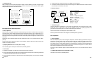
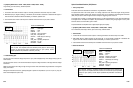
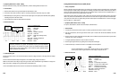
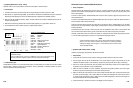
• Troubleshooting Tips
If the amplitude is low, look for an excessive air gap between the trigger wheel and the pickup.
If the amplitude wavers, look for a bent trigger wheel or shaft.
If one of the oscillations look distorted, look for a bent or damaged tooth on the trigger wheel.
IMPORTANT:
When troubleshooting a missing VSS signal, check the fuse first. If there is no power to the buffer,
there will be no square wave output. If the fuse is good, check the sensor first than a buffer mounted
under the dash. If you have a sine wave coming from the sensor, but no square wave from the buffer,
don’t assume the problem is in the buffer; it may not be there because of a loose connector between
the sensor and the buffer.
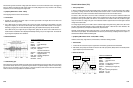
Optical Vehicle Speed Sensor (VSS)
• Theory of Operation
The optical vehicle speed sensors are usually driven by a conventional cable and are found under the dash. They
are digital sensors and are not affected by electromagnetic interference (EMI).
They generally consist o
f
a rotating disk
with slots in it, two fiber optic light pipes, a light emit
t
ing diode, and a
phototransistor as the light sensor. An amplifier is coupled to the phototransistor to create a strong enough signal for
use by other
electronic devices
,
such as the PCM or ignition module. The phototransistor and amplifier create a
digital output signal (on/off pulse).
Optical sensors are very susceptible to malfunction from dirt or oil interfering with the light transmission through the
rotating disk. When dir
t
or oil enters into the sensitive areas of the
sensors
,
driveability problems
can occur and
DTC’s can be set.
6-21
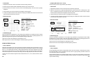
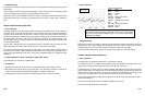
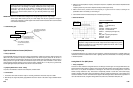
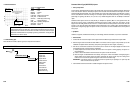
The amplitude and frequency increase with
vehicle
speed
.
Vehicle Speed Sensors
make waveforms whose
shapes all look and behave v ery similar. Generally,
t
he
oscillations (the ups and downs
in the waveform) are
very symmetrical at
constan
t
speed.
P - P = 6.93 V
FREQ = 131 Hz
AC signal - Amplitude & Frequency
increase with vehicle speed.
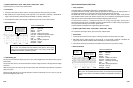
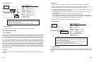
• Troubleshooting Tips
The duty cycle of the waveform changes only when a “sync” pulse is displayed. Any other changes in duty cycle can
mean troubles.
The top and bottom corners of the waveform should be sharp. However, the left upper corner may appear rounded
on some of the higher frequency (high data rate) optical distributors. This is normal.
Optical CMP sensors are very susceptible to malfunction from dirt or oil interfering with the light transmission through
the rotating disk.
When dirt or oil enters into the sensitive areas of the sensors, no starts, stalls, or misfires can occur.
Magnetic Vehicle Speed Sensor (VSS)
•
Theory of Operation
The vehicle speed sensors provides vehicle speed information to the PCM, the cruise control, and the speedometer.
The PCM uses the data to decide when to engage the transmission torque converter clutch lockup and to control
electronic transmission shift levels, cruise control, idle air bypass, engine cooling fan, and other functions.
The magnetic vehicle speed sensors are usually mounted directly on the transmissions or transaxles. They are two
wire sensors and AC signal generating analog sensors. They are very susceptible to Electromagnetic Interference
(EMI or RF) from other electronic devices on the vehicle.
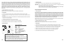
They generally consist o
f
a wire wrapped, soft bar magnet wi
t
h two connections. These
t
wo
winding
,
or coil,
connections are
t
he sensor’s output terminals.
When a ring gear (a reluctor wheel) rotates past this sensor, it
induces a voltage in the winding.
A uniform tooth pattern on the reluctor wheel produces a sinusoidal series of pulses having a consistent shape. The
amplitude is proportional to the rotating speed of the reluctor wheel. The signal frequency is based on the rotational
speed o
f
the reluctor. The
air gap between the sensor’s
magnetic tip and the reluctor wheel greatly
affects the
sensor’s signal amplitude.
• Symptoms [OBD II DTC’s: P0500 ~ P0503]
Inaccurate speedometer, improper transmission shifting, problems affecting ABS and cruise control
• Test Procedure
1. Raise the drive wheels off the ground and place the transmission in drive.
2.
Connect the CH A lead to the sensor output or HI and its ground lead to the sensor output LO or GND.
3. With KOBD (Key On, Being Driven), monitor the VSS output signal at low speed while gradually increasing the
speed of the drive wheels.
4. Use the Glitch Snare mode to detect spikes and dropouts.
6-20