


• Symptoms
Slow and improper shifting, engine stops running when vehicle comes to a stop
• Test Procedure
1. Connect the CH A lead to the transmission shift solenoid control signal from the PCM and its ground lead to the
chassis GND.
2. Drive the
vehicle
as needed
t
o make the
driveability problem
occur or
t
o exercise
the suspected shift
solenoid circuit.
3. Make sure that the amplitude is correct for the suspected transmission operation.
4. Use the proper transmission fluid pressure gauges to make sure the transmission fluid pressure and flow being
controlled by the solenoid is being effected properly by solenoid operation. This will help discriminate between an
electronic problem and
a mechanical problem (such as a sticking solenoid valve,
clogged
f
luid passages
,
or
leaking internal seals, etc.) in the transmission.
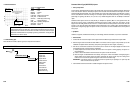
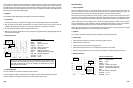
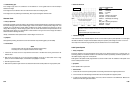
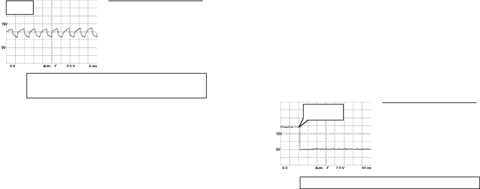
• Reference Waveform
VEHICLE INFORMATIONS
YEAR
:
1993
MAKE : Ford
MODEL : Explorer
ENGINE : 4.0 L
FUELSYS :
Multiport Fuel Injection
PCM_PIN : 52 Org Yel wire
STATUS : KOBD (Key On Driven)
RPM
:
1500
ENG_TMP : Operating Temperature
VACUUM
: 19 In. Hg
MILEAGE : 54567
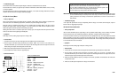
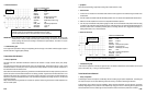
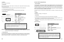
• Troubleshooting Tips
If the waveform appears as a flat line (no signal at all), it can indicate a PCM failure, PCM conditions not met (shift
points, TCC lockup, etc.), or wiring or connector problems.
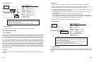
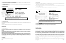
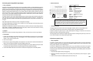
Turbo Boost Control Solenoid
• Theory of Operation
Turbochargers increase horsepower considerably withou
t
increasing engine piston displacement
.
Turbochargers
also improve torques over the useful RPM range and fuel economy, and reduces exhaust gas emissions.
Turbocharger’s boost pressure must
be regula
t
ed to obtain optimum acceleration, throttle response, and engine
durability. Regulating the boost pressure is accomplished by varying the amount of exhaust gas that bypasses the
exhaust side turbine. As more exhaust gas is routed around the turbine, the less boost pressure is increased.
6-45
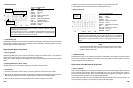
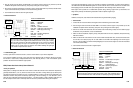
The drive signal should be consistent and repeatable.
Vehicle speed reached
35 MPH here and PCM
turned shift solenoid on
• Reference Waveform
VEHICLE INFORMATIONS
YEAR
:
1993
MAKE : Ford
MODEL : Explorer
ENGINE : 4.0 L
FUELSYS :
Multiport Fuel Injection
PCM_PIN : 21 Wht-LtBlu wire
STATUS :
KOER (Key On Running)
RPM : Idle
ENG_TMP : Operating Temperature
VACUUM : 19 In. Hg
MILEAGE : 54567
IMPORTANT :Before diagnosing
IAC solenoid, several things must be checked and
verified;
t
he thro
t
tle plate
should be free of carbon buildup and should open and close freely, the minimum air rate (minimum
throttle opening) should be se
t
according to
manufacturer’s specifications,
and check
for vacuum
leaks or false air leaks.
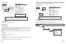
• Troubleshooting Tips
If the engine idle speed doesn’t change corresponding with the change of the PCM’s command signal, suspect a
bad IAC solenoid or clogged bypass passage.
Transmission Shift Solenoid
• Theory of Operation
The PCM controls an au
t
oma
t
ic transmission’s electronic shift solenoid
or
torque conver
t
er clutch
(TCC)
lockup
solenoid.
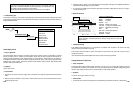
The PCM opens and closes the solenoid valves using a DC switched signal. These solenoid valves, in effect, control
transmission fluid flow to clutch park, servos, torque converter lockup clutches, and other functional components of
the transmission under the PCM’s control.
Some electronic shift solenoid systems use ground feed controlled solenoids that are always powered up and some
systems use power feed controlled solenoids that are always grounded. A ground feed controlled solenoid on a DC
switched circuit appears as a straight line at the system voltage, and drops to ground when the PCM activates the
solenoid. A power feed controlled solenoid on a DC switched circuit appears as a straight line at 0 V until the PCM
activates the solenoid.
Many vehicle PCM’s are programmed not to enable TCC operation until the engine reaches a certain temperature as
well as a certain speed.
6-44
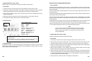
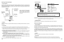
The idle control output command from the PCM should change when accessories are
switched on and off or the transmission is switched in and out of gear.
DC level should decrease as the IAC solenoid drive current is increased.
FREQ = 158 Hz
MAX = 12.2 V
MIN = 6.40 V