


4. Press the HOLD key to freeze the waveform on the display for closer inspection.
5. To measure resistance, disconnect the sensor before changing to the GMM mode and then connect the Ground
and CH A leads to the terminals on the sensor.
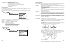
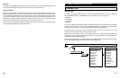
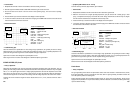
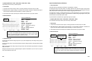
• Reference Waveform
VEHICLE INFORMATION
YEAR : 1986
MAKE : Oldsmobile
MODEL
:
Toronado
ENGINE : 3.8 L
FUELSYS : Multiport Fuel Injection
PCM_PIN : C10 Yel wire
STATUS : KOER (Key On Running)
RPM : 1500
ENG_TMP : Warming Up
VACUUM : 18 In. Hg
MILEAGE : 123686
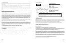
• Troubleshooting Tips
Check the manufacturer’s specifications for exact voltage range specifications, but generally the sensor’s voltage
should range from 3 V to just under 5 V when stone cold, dropping to around 1 V at operating temperature. The
good sensor must generate a signal with a certain amplitude at any given temperature.
Opens in the ECT sensor circuit will appear as upward spikes to V Ref.
Shorts to ground in the ECT sensor circuit will appear as downward spikes to ground level.
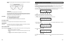
Fuel Temp Sensor
• Theory of Operation
Most Fuel Temperature (FT) sensors are Negative Temperature Coefficient (NTC)
t
ype thermistors. They are
primarily
t
wo wire
analog sensors whose resistance decreases when their temperature increases. Some sensors
use their own case as a ground, so they have only one wire, the signal wire. They are supplied with a 5 V V Ref
power signal and return a voltage signal proportional to the temperature to the PCM. FT sensors usually sense the
engine’s fuel temperature in the fuel rail. When this instrument is connected to the signal from a FT sensor, what is
being read is the voltage drop across the sensor’s NTC resistor.
Typically, FT sensor’s resistance ranges from about 100,000 ohms at -40 °F (-40 °C) to about 50 ohms at +266 °F
(+130 °C).
• Symptoms [OBD II DTC’s: P0180 ~ P0184, P0185 ~ P0189]
Hard start, poor fuel economy, driveability problems
6-7
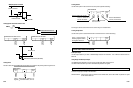
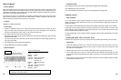
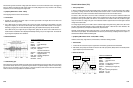
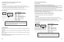
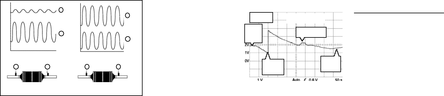
Stone
cold
here
63.5 Dg.F
Thermostat opens
here
ECT Test from stone
cold to operating temp.
MAX = 3.26 V
MIN = 1.86 V
PCM resistor
switched in
here
Engine at
operating
temp. here
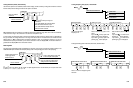
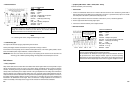
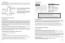
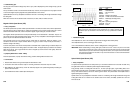
• Troubleshooting Tips
When a catalytic converter is totally deteriorated, the catalytic conversion efficiency as well as the oxygen storage
capability of the catalytic converter are essentially lost. Therefore, the upstream and downstream O
2
sensor signals
closely resemble one another on an inactive converter.
ECT (Engine Coolant Temperature) Sensor
• Theory of Operation
Most ECT sensors are Negative Temperature Coefficient (NTC) type thermistors. This means they are primarily two
wire analog sensors whose resistance decreases when their temperature increases. They are supplied with a 5 V V
Ref power signal and return a voltage signal proportional to the engine coolant temperature to the PCM. When this
instrument is connected to the signal from an ECT sensor, what is being read is the voltage drop across the sensor’s
NTC resistor.
Typically, ETC sensor’s resistance ranges from about 100,000 ohms at -40 °F (-40 °C) to about 50 ohms at +266 °F
(+130 °C).
The ETC sensor signal is used by the PCM to control closed-loop operation, shift points, torque converter clutch
operation, and cooling fan operation.
• Symptoms [OBD II DTC’s: P0115 ~ P0116, P0117 ~ P0119]
No or hard start, high fuel consumption, emissions failure, driveability problems.
• Test Procedure
1.
Backprobe the terminals on the ECT sensor with the CH A lead and its ground lead.
2. Run the engine at idle and monitor the sensor voltage decrease as the engine warms. (Start the engine and hold
the throttle at 2500 RPM until the trace goes across the screen.)
3. Set the time base to
50 sec/div to
see the sensor’s entire operating range
,
from stone cold to operating
temperature.
6-6
V
t
V
t
B
A
BA
B
A
BA
upstream sensor downstream sensor
Catalytic Converter OK Catalytic Converter Efficiency
poor