


Throttle Position Sensor (TPS)
•
Theory of Operation
A TPS is a variable resistor that tells the PCM the position of the throttle, that is, how far the throttle is open, whether
it is opening or closing and how fast. Most throttle position sensors consist of a contact connected to the throttle
shaft which slides over a section of resistance material around the pivot axis for the movable contact.
The TPS is a three wire sensor. One of the wires is connected to an end of the sensor’s resistance material and
provides 5 V via the PCM’s V Ref circuit, another wire is connected to the other end of the resistance material and
provides the sensor ground (GND). The
third
wire is connected to
t
he movable contact and provides the signal
output to the PCM. The voltage at any point in the resistance material is proportional to the throttle angle as sensed
through the movable contact.
The voltage signal returning to the PCM is used to calculate engine load, ignition timing, EGR control, idle control
and other
PCM controlled parameters such as
t
ransmission
shif
t
points. A
bad
TPS
can cause
hesitation,
idle
problems, high emissions, and Inspection/ Maintenance (I/M) test failures.
Generally, throttle position sensors produce just under 1 V with the throttle closed and produce just under 5 V with
the throttle wide open (WOT). The PCM determines the sensor’s performance by comparing the sensor output to a
calculated value based on MAP and RPM signals.
• Symptoms [OBD II DTC’s: P0120 ~ P0124, P0220 ~ P0229]
Hesitation, stall at stops, high emissions, I/M test failures, transmission shifting problems.
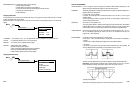
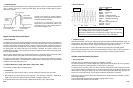
• Test Procedure
1. Connect the CH A lead to the output or signal circuit of TPS and its ground lead to the TPS’s GND.
2. With KOEO, slowly sweep the throttle from closed to the wide open position (WOT) and then the closed position
again. Repeat this process several times.
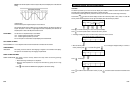
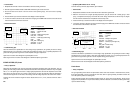
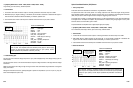
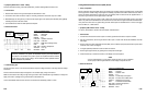
• Reference Waveform
VEHICLE INFORMATION
YEAR : 1989
MAKE : Chevrolet
MODEL :
1500 Series Truck
ENGINE : 5.0 L
FUELSYS : Throttle Body Fuel Injection
PCM_PIN : C13 DkBlu wire
STATUS :
KOEO (Key On Engine Off)
RPM : 0
ENG_TMP : Operating Temperature
VACUUM : 0 In. Hg
MILEAGE : 108706
6-11
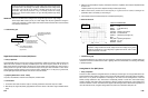
MAX = 4.36 V
MIN = 880 mV
Closed Throttle Closed Throttle
Wide Open Throttle
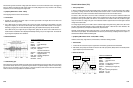
Knock sensors generate a small AC voltage spike when vibration or a knock from detonation occurs. The bigger the
Knock or vibration, the bigger the spike. Knock sensors are usually designed to be very sensitive to the Knocking
frequencies (in 5 to 15 kHz range) of the engine block.
• Symptoms [OBD II DTC’s: P0324 ~ P0334]
No AC signal generation at all from Knock Sensors.
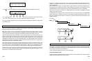
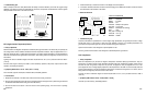
• Test Procedure
1. Connect the CH A lead to the sensor output or HI and its ground lead to the engine block or the sensor wire
labeled LO (if internally grounded).
2. Tes
t
1: With the
K
ey On, Engine Running, pu
t
a load on the engine and watch the Scope display. The peak
voltage and
frequency of the waveform will increase with
engine load and RPM increment. If
the engine is
detonating or pinging from too much advanced ignition timing, the amplitude and frequency will also increase.
Test 2: With the
Key On, Engine Of
f
, tap
the engine block lightly near
the sensor with a
small
hammer or a
ratchet extension. Oscillations will be displayed immediately following a tap on the engine block. The harder the
tap, the larger the amplitude of the oscillations.
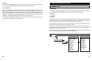
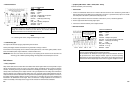
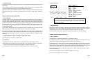
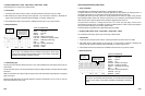
• Reference Waveform
VEHICLE INFORMATION
YEAR : 1993
MAKE : Ford
MODEL : F150 4WD Pickup
ENGINE
:
5.0 L
FUELSYS
:
Multiport Fuel Injection
PCM_PIN : Neg-GND
Pos-Pin23 Yel Red wire
STATUS
:
KOER (Key On Running)
RPM : Slightly Accelerate
ENG_TMP : Operating Temperature
VACUUM
: 19 In. Hg
MILEAGE : 66748
• Troubleshooting Tips
Knock sensors are extremely durable and usually fail from physical damage to the sensor itself. The most common
type of Knock Sensor failure is not to generate a signal at all due to its physical damage, when the waveform stays
flat even if you rev the engine or tap on the sensor. In this case, check the sensor and the instrument connections;
make sure the circuit is not grounded, then condemn the sensor.
6-10
Typical Knock Sensor test.
Note signal goes above and below zero volts(AC).
Logged during slight acceleration.