


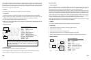
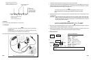
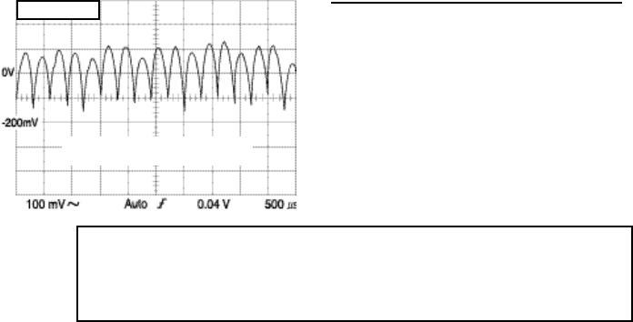
• Reference Waveform
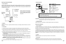
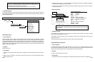
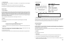
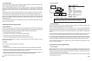
VEHICLE INFORMATIONS
YEAR
:
1986
MAKE : Oldsmobile
MODEL : Toronado
ENGINE : 3.8 L
FUELSYS : Multiport Fuel Injection
PCM_PIN :
B+ post at alternator
STATUS : KOER (Key On Running)
RPM : Idle
ENG_TMP : Operating Temperature
VACUUM
:
18 In. Hg
MILEAGE : 123686
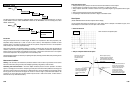
• Troubleshooting Tips
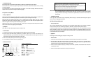
If the waveform has very noticeable dropouts with two or three times the peak to peak amplitude of a normal ripple,
the diodes are defective. Dropouts from bad diodes usually have a peak to peak voltages of around 1.5 V to 2.0 V.
If the humps in the waveform are grouped into pairs, the alternator has one or more bad diodes.
Audio System Speaker
• Theory of Operation
Automotive speakers
are electromechanical
devices that
convert electrical signal from a vehicle’s
radio (or
monitoring system) into mechanical vibrations. The mechanical vibrations produced by automotive speakers are in
the audible frequency range from 16 to 20,000 Hz.
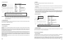
Audio signals to the speaker usually range between 0.5 and 10 V Peak to Peak. DC resistance of the speaker voice
coils is normally less then 10 ohms.
•
Symptoms
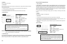
A blown speaker with an open circuit
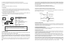
• Test Procedure
1. Connect the CH A lead to the positive speaker circuit and its ground lead to the negative speaker circuit.
2. Turn on the radio at normal listening level and make sure that the speaker drive signal is present.
3. To measure the resistance o
f
the speaker voice coils, se
t
the instrument to the
GMM mode. Measure the
resistance with the drive signal disconnected.
6-55
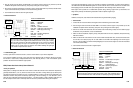
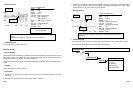
A bad alternator diode produces Peak to Peak voltages exceeding 2 V usually and its
waveform will have “humps” that drop out and go much lower than the normal ones
shown above.
A shorted diode splits the pulses into pairs.
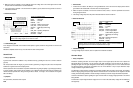
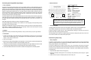
P-P = 373 mV
Tested at idle with high beam and wipers
on, and A/C blower on high speed.
• Troubleshooting Tips
If the voltage is high, there is no command to turn the alternator on or the regulator does not have the ability to
decrease the voltage.
If the voltage is low, the alternator will be on all the time and cause an overcharging state.
If the voltage can not be pulled to ground sufficiently, there may be bad regulator within the PCM.
Alternator Diode
• Theory of Operation
An alternator generates current and voltage by the principles of electromagnetic induction. Accessories connected to
the vehicle’s charging system require a steady supply of direct current (DC) at a relatively steady voltage level. A set
of diodes, part of
the alternator’s rectifier
bridge, modifies the
AC voltage (produced in the
alternator) to the DC
voltage. When analyzing a vehicle’s charging system, both AC and DC level should be analyzed because the AC
level (called “ripple voltage”) is a clear indication of diode condition. Too high a level of AC voltage can indicate a
defective diode and discharge the battery.
Usually, a bad alternator diode produces Peak to Peak voltages of more than 2 V.
• Symptoms
Overnight battery draining, excessive AC current from alternator output, flickering lights, poor driveability
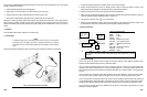
• Test Procedure
NOTE
This test is made at the rear case half of the alternator and not battery.
The battery can act as a capacitor and absorb the AC voltage.
1. Connect the CH A lead to
the B+ output
t
erminal on
t
he back of the alternator and its ground lead
to the
alternator case.
2. With the Key On, Engine Off, turn
on the high
beam headlights, put the
A/C or heater blower motor
on high
speed, turn on the windshield wipers, and rear defrost (if equipped) for 3 minutes.
3. Start the engine and let it idle.
4. Make sure that pulses in ripple waveform are all about the same size and that pulses are not grouped into pairs.
6-54