


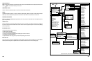
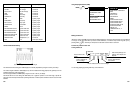
5.1 INSTRUMENT TEST MODES
From the MAIN MENU, you can choose 3 independent instrument test modes:
• COMPONENT TESTS
• SCOPE
• GRAPHING MULTIMETER
The fastest way to set up the instrument to test most devices and circuits is to choose from one of the built in
COMPONENT TESTS. These
tests preset the instrument to either Single or Dual Input Scope mode. Most
instrument settings may be adjusted manually once you have chosen a Component Test, enabling you to fine tune
set
t
ings to get a better look a
t
the
signal. Changes
you make to se
t
tings specific
to a Component Test are
temporary, and are restored to their preset values each time another test is chosen. When configured for a specific
Component Test, the instrument displays the reference waveform and data as well as the name of the test on the
bottom display along with the Function Key Labels specific to the test chosen.
If you prefer total control over your instrument configuration, choose SCOPE test mode from the MAIN MENU.
Settings for SCOPE are separately preserved and restored each time you choose SCOPE from the MAIN MENU.
These se
t
tings are not affec
t
ed when
you choose a Component Test. This is also
true for the GRAPHING
MULTIMETER test mode, so in effect they are “custom” setups.
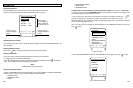
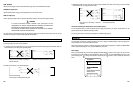
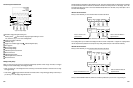
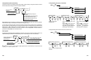
5.2 SCOPE DISPLAYS
Using Single and Dual Input Scope Mode
The instrument can be configured to show scope displays for either CH A or CH B signals: In DUAL INPUT SCOPE
mode, both CH A and CH B may be displayed at the same time.
Use SINGLE INPUT SCOPE mode if you want to measure a single signal, INPUT B is turned off.
Use DUAL INPUT SCOPE mode if you want to simultaneously measure two signals.
MEMU ( )
5-1
5. INSTRUMENT OPERATION
SCOPE
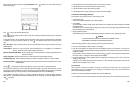
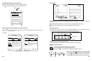
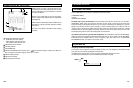
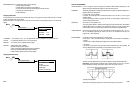
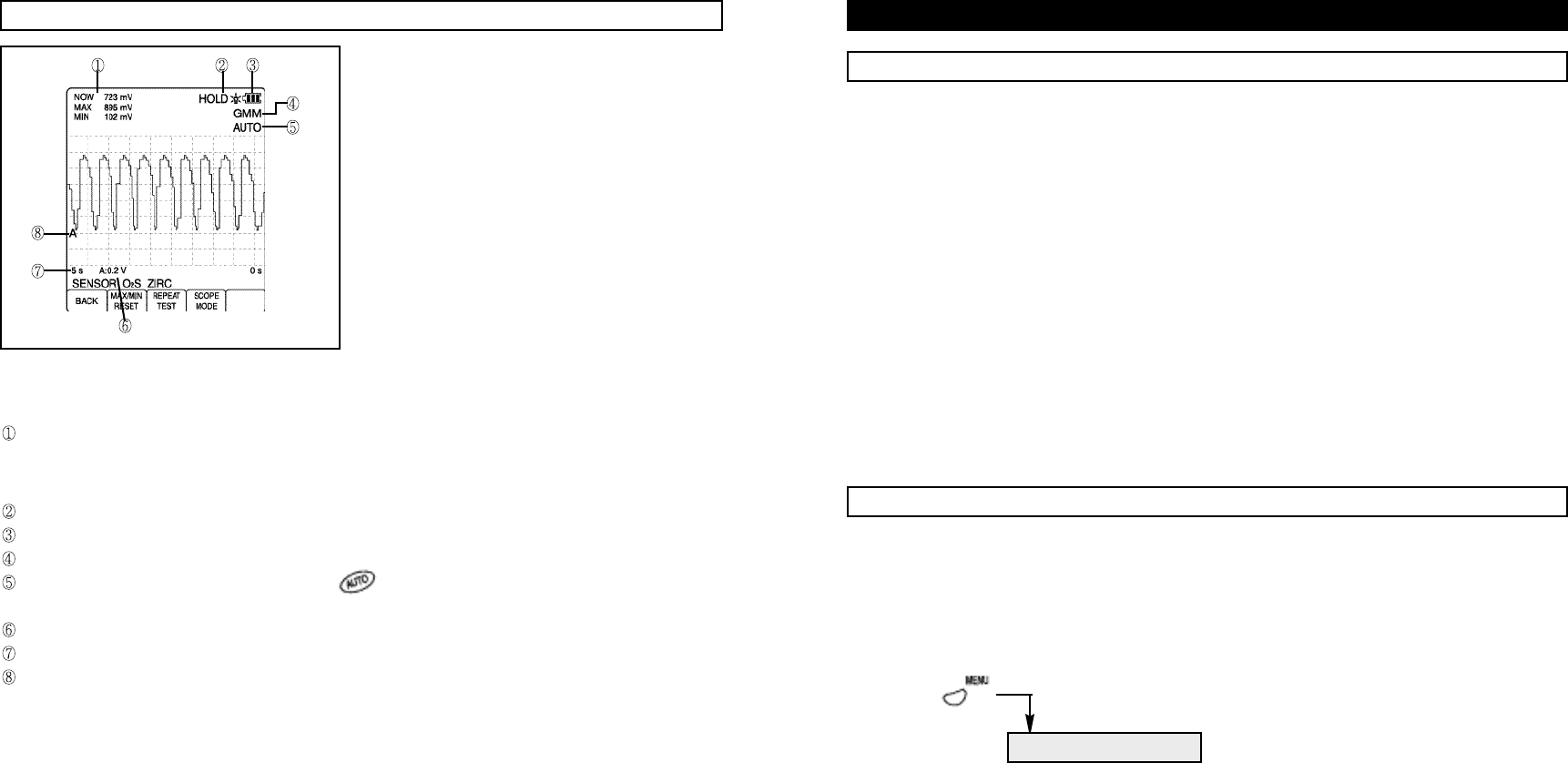
4.8 GMM (GRAPHING MULTIMETER) MODE
GMM mode plots the results of signal measurements such
as frequency as the values change wi
t
h time
.
The time
range in GMM mode may be set manually from 5 seconds
to 24 hours per display.
Ranges
for
the vertical scale may also
be set manually,
and the available range depends upon the measurement
being displayed.
Where possible, measurements plotted in GMM mode are
performed on a cycle-by-cycle basis, resulting in extremely
fast response.
This mode is very suitable to find faults in slowly changing
processes.
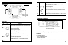
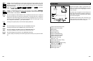
Indicate meter measurement functions.
NOW:Most recent meter reading.
MAX: Maximum value since last reset.
MIN: Minimum value since last reset.
Indicate HOLD function enabled.
Low battery indicator.
Indicate GMM mode.
Indicate AUTORANGING mode. Pressing AUTO ( ) sets automatic ranging on. Using the Four Way arrow
keys for ranging turns automatic ranging off and extinguishes AUTO.
Indicate voltage per division.
Indicate time per display.
Indicate signal source channel.
4-16
Figure 10. GMM Mode Indicators