


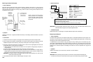
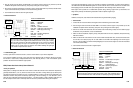
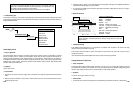
How much and when EGR flow occurs is very important to emissions and driveability. To precise control EGR flow,
the PCM sends Pulse Width Modulated signals to a vacuum solenoid valve to control vacuum flow to the EGR valve.
When applying vacuum, the EGR valve opens, allowing EGR flow. When blocking vacuum, EGR flow stops.
Most engine
control systems do not enable EGR operation during
cranking
,
engine warm up, deceleration, and
idling. EGR is precisely controlled during acceleration modes to optimize engine torque.
• Symptoms
Hesitation, loose power, stall, emissions with excessive NOx, engine detonation (pinging)
• Test Procedure
1. Connect the CH A lead to the EGR control signal from the PCM and its ground lead to GND.
2. Start the engine and hold throttle at 2500 R
P
M for 2-3 minutes until
t
he engine is fully warmed up and the
Feedback Fuel System enters closed loop. (Verify this this by viewing the O
2
sensor signal.)
3. Shut off A/C and all other accessories. Drive the vehicle under normal driving modes; start from dead stop, light
acceleration, heavy acceleration, cruise, and deceleration.
4. Make sure that the amplitude, frequency, shape, and pulse width are all correct, repeatable, and present during
EGR flow conditions.
5. Make sure that all the hoses and lines to and from the intake manifold, EGR valve, and vacuum solenoid valve
are
all intact, and routed properly,
with no leaks. Make sure the EGR valve diaphragm can hold the
proper
amount of vacuum. Make sure that the EGR passageways in and around the engine are clear and unrestricted
from internal carbon buildup.
6. Use the Glitch Snare mode to check for signal dropouts.
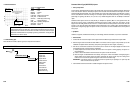
• Reference Waveform
VEHICLE INFORMATIONS
YEAR
:
1990
MAKE : Chevrolet
MODEL : Suburban
ENGINE : 5.7 L
FUELSYS : Throttle Body Fuel Injection
PCM_PIN
:
A4 Gry wire
STATUS : KOER (Key On Running)
RPM : Light Acceleration
ENG_TMP : Operating Temperature
VACUUM : 12-23 In. Hg
MILEAGE : 59726
6-41
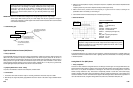
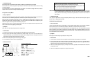
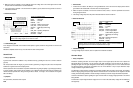
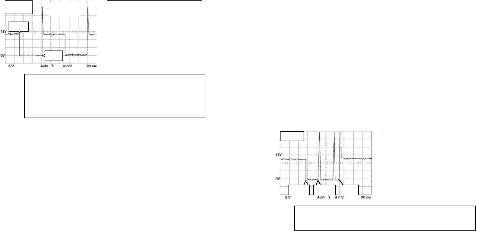
As soon as
the engine
reaches the predetermined EGR requirement conditions,
the
PCM should begin pulsing the EGR solenoid with a pulse width modulated signal to
open the EGR solenoid valve. EGR demands are especially high during accelerations.
MAX = 29.0 V
MIN = -1.33 V
PCM turns
circuit on
PCM pulses
circuit here
PCM turns
circuit off
2. Start the engine and hold
throttle at
2500 RPM for 2-3 minutes until the engine is fully
warmed up
and
t
he
Feedback Fuel System enters closed loop. (Verify this by viewing the O
2
sensor signal.)
3. Shut off A/C and all other accessories. Put vehicle in park or neutral. Adjust lean stop, air bleed, and idle mixture
as per recommended service procedures for the carburetor being serviced.
4. Use the Glitch Snare mode the check for signal dropouts.
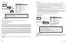
• Reference Waveform
VEHICLE INFORMATIONS
YEAR
:
1984
MAKE : Oldsmobile
MODEL : Delta 88
ENGINE : 5.0 L
FUELSYS : Feedback Carburetor
PCM_PIN
:
18 Blu wire (at test connector)
STATUS
:
KOER (Key On Running)
RPM : Idle
ENG_TMP : Operating Temperature
VACUUM : 19.5 In. Hg
MILEAGE : 104402
• Troubleshooting Tips
If the duty cycle does not remain around 50 %, check for vacuum leaks or a poor mixture adjustment.
If the waveform oscillates around 50 % duty cycle during one operating mode (for instance, idle) but not another,
then check
f
or
vacuum leaks,
misadjusted
idle mixture, main metering
mixture, or other non-feedback system
problems that affect mixture at different engine speeds.
EGR (Exhaust Gas Recirculation) Control Solenoid
• Theory of Operation
EGR systems are designed
t
o dilute
t
he air-fuel mixture and limit
NOx formation when combustion temperatures
generally exceed 2500 °F (1371 °C) and air-fuel ratios are lean. The effect of mixing exhaust gas (a relatively inert
gas) with the incoming air-fuel mixture is a sort of chemical buffering or cooling of the air and fuel molecules in the
combustion chamber. This prevents excessively rapid burning of
the air-fuel charge, or even detonation, both o
f
which can raise combustion temperatures above 2500 °F. The initial formation of NOx is limited by EGR flow and
then the catalytic converter acts to chemically reduce the amounts of produced NOx entering the atmosphere.
6-40
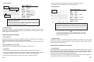
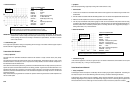
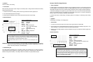
When the main
venturi metering
circui
t
s
are adjusted properly
(lean stop, air bleed,
etc.), the mixture con
t
rol signal should oscillate around 50 % duty cycle
normally
.
When the main metering and idle mixture adjustments are set correctly, the tall spike
will oscillate
slightly from
right
to left and back again
,
but remain very
close
to the
middle of the two vertical drops in the waveform. The PCM is oscillating the signal right
to left, based on input from the O
2
sensor.
FREQ = 10.0 Hz
DUTY = 48.8 %
MAX = 31.6 V
PCM turns
circuit off
PCM turns
circuit on
NOTE: O
2
sensor
must be good to
test this circuit