


Diesel Glow Plug
• Theory of Operation
Starting cold diesel engines are not easy because Blowby past the
piston rings and thermal losses reduce the
amount of
compression possible. Cold starting
can be improved by a shea
t
hed element glow plug in
t
he
precombustion chamber (in case of Direct-injection (DI) engines, in the main combustian chamber).
When current flows through the heating coil of the glow plug, a portion of the fuel around the glow plug’s hot tip is
vaporized to assist in igniting the air-fuel mixture. Newer glow plug systems, which continue to operate after engine
startup for up to 3 minutes, improve initial engine performance, reduce smokes, emissions, and combustian noises.
Usually, a glow plug control unit supplies power to the glow plug during appropriate conditions. Some newer glow
plugs
are designed with a heater element that changes resis
t
ance wi
t
h temperature.
The glow plug’s resistance
increases as the heating element gets hotter by the combustian temperature’s increment after startup.
Usually, glow plug systems are power feed controlled so the waveform of the
current
going
t
hrough
its heating
element appears as a straight line at 0 V until the ignition key is switched on.
• Symptoms
No or hard start, emissions with excessive smokes, excessive combustian noises (knocks)
• Test Procedure
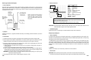
1. Set the instrument up with the current probe. (Connect the probe to the CH A.)
2. Adjust the probe to read DC Zero.
3. Clamp the current probe around the glow plug feed wire.
4. With the diesel engine stone cold, turn on the ignition key and watch for the readings.
5. Make sure that the amplitude of the current is correct and consistent for the glow plug systems under test.
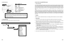
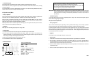
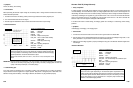
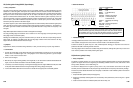
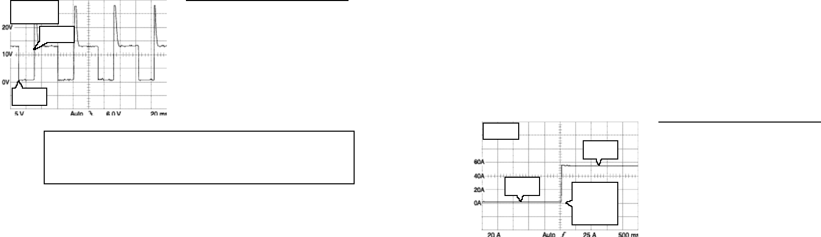
• Reference Waveform
VEHICLE INFORMATIONS
YEAR
:
1977
MAKE : Mercedes-Benz
MODEL : 240 D
ENGINE : 2.4 L
FUELSYS : Multiport Fuel Injection
PCM_PIN : Power supply to glow plugs
STATUS
:
KOEO (Key On Engine Off)
RPM : 0
ENG_TMP : Ambient Temperature
VACUUM
: 0 In. Hg
MILEAGE
: 151417
6-47
MAX = 56 A
MIN = 1 A
Ignition key
switched on.
Current begins
to flow through
glow plugs.
Ignition key
on
Ignition key
off
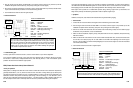
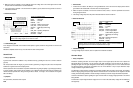
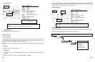
A door (called the wastegate) is opened and closed to regulate the amount of bypass. The wastegate is controlled
by a vacuum servo motor, which can be controlled by a vacuum solenoid valve that receives a control signal from
the PCM. When the PCM receives a signal from the MAP sensor indicating that certain boost pressure is reached,
the PCM commands the vacuum solenoid valve to open in order to decrease boost pressure. The PCM opens the
solenoid valve via a pulse width modulated signal.
• Symptoms
Poor driveability, engine damage (blown head gasket), hard stall under acceleration
• Test Procedure
1. Connect the CH A lead to the solenoid control signal from the PCM and its ground lead to the chassis GND.
2.
S
tart the
engine and
hold thro
t
tle at 2500 RPM
for
2-3 minu
t
es until the engine is
f
ully warmed
up and the
Feedback Fuel system enters closed loop. (Verify this by viewing the O
2
sensor signal, if necessary.)
3. Drive the vehicle as needed to make the suspected problem occur.
4. Make sure that the drive signal comes on as the boost pressure is regulated and the wastegate actually responds
to the solenoid control signal.
•
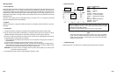
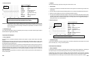
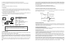
Reference Waveform
VEHICLE INFORMATIONS
YEAR
:
1988
MAKE : Chrysler
MODEL : LeBaron Convertible
ENGINE :
2.2 L Turbo
FUELSYS : Multiport Fuel Injection
PCM_PIN : 39 LtGrn Blk wire
STATUS : KOBD (Key On Driven)
RPM : Moderate Acceleration (35 MPH)
ENG_TMP : Operating Temperature
VACUUM : 5 In. Hg
MILEAGE : 77008
• Troubleshooting Tips
If the turn off spikes are not present, the solenoid coil may be shorted.
If the drive signal never appears under the high boost conditions, the driver within the PCM may have failed.
If the turn off spikes are runted (shortened), the vacuum solenoid valve may be shorted.
6-46
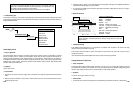
As soon as the turbo engine reaches a predetermined
boost pressure under
acceleration,
t
he PCM should begin pulsing the turbo boost
solenoid wi
t
h a varying
pulse width modulated signal
t
o open the was
t
ega
t
e. On deceleration, the signal is
stopped and the valve is closed.
FREQ = 19.5 Hz
DUTY = 39.2 %
MAX = 28.0 V
PCM turns
circuit on
PCM turns
circuit off