


Vehicle manufacturers have
helped you locate a driveability problem by designing Electronic Control Units with
trouble-code generating capabilities. But, the ECUs aren’t perfect because they don’t cover everything (most glitches
and intermittents)
.
On-board diagnostic systems are engineered with
f
airly wide
set limits
f
or
sensors,
actuators,
connectors and terminals. When a component exceeds its limit consistently, a trouble code is generated. But to keep
warranty costs in line, tolerances aren’t set to catch all transients, even though they can cause some of your worst
driveability problems.
Therefore, repair technicians are finding more and more uses for a Digital Storage Oscilloscope (DSO) and a Digital
Multimeter (DMM) thesedays.
A DSO can capture
a live
“signa
t
ure” of a circuit and store it for later analysis or
comparison against Known-good waveforms - an invaluable resource for detecting marginal components. A GMM
(Graphing Multimeter) gives you advanced multimeter capabilities coupled with the visual power of trend graphing
and waveform display.
This Meter a combination DSO and GMM represents
t
he most powerful and versatile
tool available for
troubleshooting automotive electronics since we can track down elusive no-code driveability problems.
1.1 COMPARING SCAN TOOLS, DSOs AND DMMs
All of these tools have unique capabilities, and today’s vehicles demand that automotive technicians are able to use
all three tools to correctly diagnose various driveability problems. DSOs alone cannot replace DMMs or scan tools.
By the same token, DMMs or scan tools cannot replace DSOs.
For example, when anti-lock brakes on your car are sometimes erratic, you might firstly try a road test to notice that
the ABS light does not come on. When you get back to the shop, you plug in your scan tool and find no trouble
codes.
Because you still have your DMM, you follow the manufacturer’s instructions and you look at the output voltage from
each of the wheel speed sensors. They all appear to be in tolerance, and the manufacturer’s fault tree recommends
you
to replace the ABS
computer
.
Un
f
or
t
unately,
t
he AB
S
computer on
t
his vehicle is embedded in
t
he master
cylinder, so you must replace everything. The worst thing is the problem still exists even after you complete all of the
work.
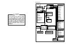
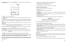
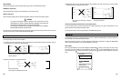
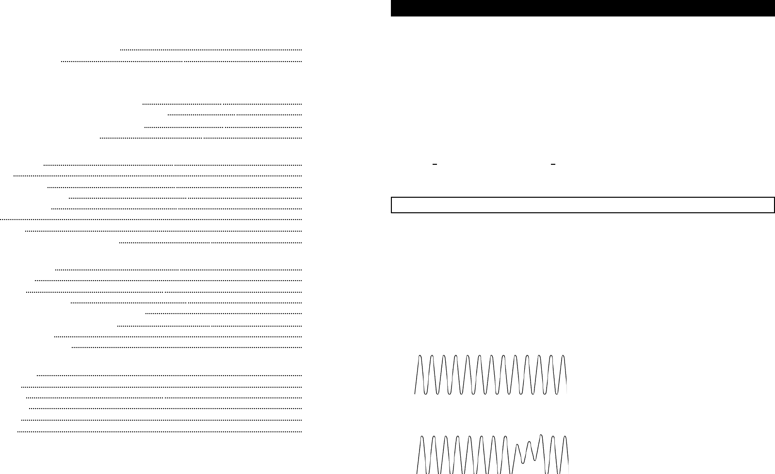
Normal ABS Signal
Most of the signal shown above is visible to scan tools, DSOs and DMMs.
Faulty ABS Signal
However, the faults shown above are not visible to scan tools and DMMs. They are only visible to DSOs.
1-1
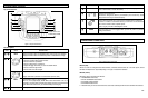
Contents
Menu Overview
1. Introduction
1.1 Comparing Scan Tools, DSOs and DMMs 1- 1
1.2 Vehicle Service Manuals 1- 2
2. Safety Information
3. Automotive Electronic Signals
3.1 Primary Signal Types Found in Modern Vehicles 3- 1
3.2 Critical Characteristics of Automotive Electronic Signals 3- 2
3.3 The Golden Rule of Electronic System Diagnosis 3- 2
3.4 Signal Probing with an Oscilloscope 3- 2
4. Getting Started
4.1 Product Description 4- 1
4.2 Quick Tour 4- 2
4.3 Front Panel Controls 4- 6
4.4 Measurement Connections 4- 7
4.5 Grounding Guidelines 4- 8
4.6 Display 4- 9
4.7 SCOPE Mode 4-15
4.8 GMM (GRAPHING MULTIMETER) Mode 4-16
5. Instrument Operation
5.1 Instrument Test Modes 5- 1
5.2
SCOPE Displays
5- 1
5.3 GMM Displays 5- 7
5.4 Dual Input Scope Operation 5-13
5.5 Changing the Vehicle Data and Instrument Setup 5-13
5.6 Freezing, Saving, and Recalling Screens 5-17
5.7 Glitch Snare Operation 5-18
5.8 Tips for Noise Management 5-19
6. Automotive Diagnostics & Applications
6.1 Component Tests 6- 1
6.2 Sensor Tests 6- 1
6.3 Actuator Tests 6-32
6.4 Electrical Tests 6-48
6.5 Ignition Tests 6-57
6.6 Diesel Tests 6-68
7. Maintenance
8. Specifications
Glossary
Menu Overview
1. INTRODUCTION