


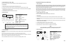
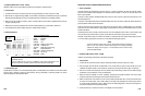
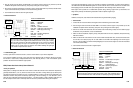
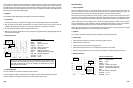
• Reference Waveform
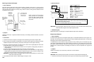
VEHICLE INFORMATIONS
YEAR
:
1986
MAKE : Nissan/Datsun
MODEL
:
Stanza Wagon
ENGINE : 2.0 L
FUELSYS : Multiport Fuel Injection
PCM_PIN : B WhtBlk wire
STATUS :
KOER (Key On Running)
RPM : Idle
ENG_TMP : Operating Temperature
VACUUM : 21 In. Hg
MILEAGE : 183513
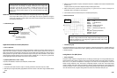
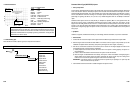
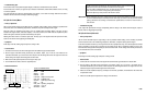
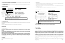
IMPORTANT :On some European
vehicles like Jaguar,
there may be only
one release spike because the
first
release spike does not appear due to a spike suppression diode.
• Troubleshooting Tips
Spikes during on-time or unusual high turn off spikes indicate the injector driver’s malfunction.
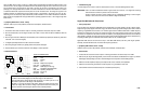
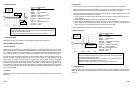
Mixture Control Solenoid
• Theory of Operation
The mixture control signal is the most important output signal in a carbureted Feedback Fuel Control system. On a
GM vehicle, this circuit pulses about 10 times per second, with each individual pulse (pulse width or on-time) varing,
depending upon the fuel mixture needed at that moment.
In a GM vehicle, this circuit controls how long (per pulse) the main jet metering rods in the carburetor stay down
(lean position). Most feedback carburetor systems operate in the same way – more mixture control on-time means
lean mixture
command. Generally, mixture
control commands (from the PCM) tha
t
oscillate around duty cycles
greater than 50 % mean the system is commanding a lean mixture in an effort to compensate for a long term rich
condition.
• Symptoms
Hesitation on throttle tip in, poor fuel economy, erratic idle, rich or lean emissions
• Test Procedure
IMPORTANT :Before performing the test procedure, the O
2
sensor must be tested and confirmed good.
1.
Connect the CH A lead to the mixture solenoid control signal from the PCM and its ground lead to GND.
6-39
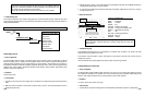
When the Feedback Fuel Control System controls
fuel mixture properly, the injector
on-time will modulate from about 1-6 ms at idle to about 6-35 ms under cold cranking
or Wide Open Throttle (WOT) operation.
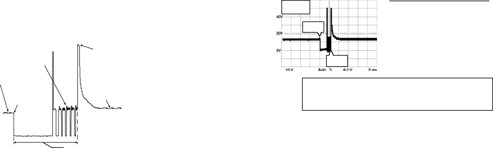
The injector coil release spike(s) ranges are from 30 V to 100 V normally.
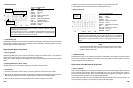
MAX = 50.6 V
MIN = -3.33 V
DUR = 2.23 ms
PCM turns
circuit off
PCM turns
circuit on
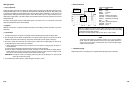
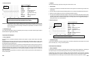
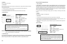
Bosch-Type Peak and Hold Injector
• Theory of Operation
Bosch type Peak and Hold injector drivers (within the PCM) are designed to allow about 4 A to flow through the
injector coil, then reduce the flow to a maximum of 1 A by pulsing the circuit on and off at a high frequency. The
other type injector drivers reduce the current by using a “switch-in” resistor, but this type drivers reduce the current
by pulsing the circuit on and off.
Bosch ty pe Peak and Hold i njector
drivers are found on a few
E
uropean
models with MFI systems and
some
early to
mid-1980s Asian vehicles with
MFI systems.
• Symptoms
Hesitation on throttle tip in, rough idle, intermittent stall at idle, poor fuel mileage, emissions test failure, low power on
acceleration
• Test Procedure
1. Connect the CH A lead to the injector control signal from the PCM and its ground lead to the injector GND.
2. Start the engine and hold
t
hrottle at
2500 RPM for 2-3 minutes until the engine is fully warmed up and
t
he
Feedback Fuel System enters closed loop. (Verify this by reviewing the O
2
sensor signal, if necessary.)
3. Shut off A/C and all other accessories. Put vehicle in park or neutral. Rev the engine slightly and watch for the
corresponding injector on-time increase on acceleration.
1) Induce propane into the intake and drive the mixture rich. If the system is working properly, the injector on-
time will decrease.
2) Create a vacuum leak and drive the mixture lean. The injector on-time will increase.
3) Raise the engine to 2500 RPM and hold it steady. The injector on-time will modulate from slightly larger to
slightly smaller as the system control the mixture. Generally, the injector on-time only has to change from 0.25
ms to 0.5 ms to drive the system through its normal full rich to full lean range.
IMPORTANT: If the injector on-time is not changing, either the system may be operating in an “open loop” idle
mode or the O
2
sensor may be bad.
4. Use the Glitch Snare mode to check for sudden changes in the injector on-time.
6-38
Peak voltage caused
by the collapse of the
injector coil. when
current is reduced.
Current flow
pulsed on and
off enough to
keep hold in
winding activated
Battery voltage
(or source voltage)
supplied to the
injector
Return to battery
(or source) voltage
Driver transistor
turns on, pulling
the injector pintle
away from its
seat, starting fuel
flow
Injector On-Time