


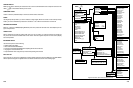
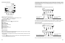
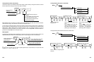
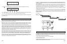
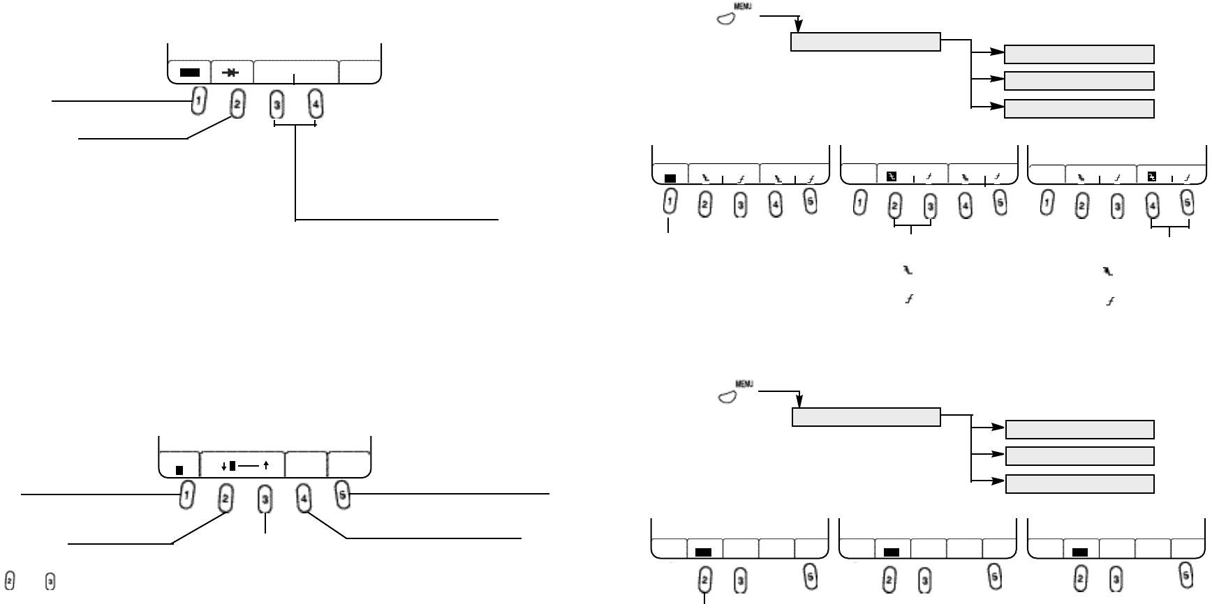
Testing Frequency, Duty Cycle, or Pulse Width
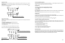
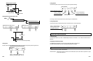
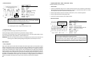
Testing Secondary Ignition Peak Volts, Burn Volts, and Burn Time
5-11
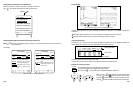
Press to test the signal
frequency in Hz.
Press to test the duty cycle of the
signal.
If you select , the duty cycle of the
negative-going pulse is displayed.
If you select , the duty cycle of the
positive-going pulse is displayed.
Press to test the pulse width of the
signal.
If you select , the width of the
negative-going pulse is displayed.
If you select , the width of the
positive-going pulse is displayed.
GRAPHING MULTIMETER
FREQUENCY
DUTY CYCLE
PULSE WIDTH
GRAPHING MULTIMETER
IGNITION PEAK VOLTS
IGNITION BURN VOLTS
IGNITION BURN TIME
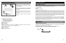
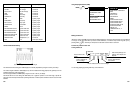
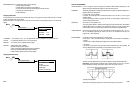
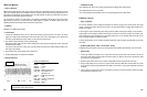
Testing Resistance, Diode, and Continuity
Use this menu option to test resistance, diode forward voltage, and the continuity of wiring and connections. Connect
the test lead tip and test lead ground across the object to be tested.
OFL is displayed when the resistance is outside the instrument’s maximum range. This occurs when the resistance
of the sensor is too high or the connection to the sensor is interrupted or open.
To test a diode, the instrument sends a small current through the diode to test the voltage across it. Depending on
the type of diode, this voltage should be in the range from 300 to 600 mV. A diode that has an internal short will
display about 0 V. OFL
is displayed when the diode is defective or when it is connected in reverse. If you are not
certain about the polarity of the diode, try the reverse connection. If this also displays OFL, the diode is defective. A
good diode must display OFL when connected in reverse.
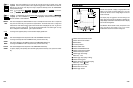
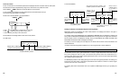
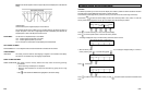
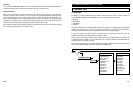
Measuring RPM
The instrument automatically scales and displays the waveform on the screen. Connect the Inductive Pickup to the
COM/TRIGGER input terminals and clamp the pickup probe on the spark plug wire close to the spark plug.
and keys are used to set the number of
S
park
Signal Pulses to
the instrument per 720 (two crank shaft
revolutions). n = 1, 2, 3, 4, 5, 6, 8, 10, or 12
5-10
Press to test continuity of wiring and
connections.
If you select OPEN, the instrument beeps
when the tested connection is open.
If you select CLOSE, it beeps when the
tested connection is closed.
MENU ( )
MENU ( )
Press to invert the displayed ignition
waveform.
Press to measure
resistance.
Press to start plotting a new graph
as new samples are acquired.
Press to decrease.
Press to increase.
Press to restore the default value
settings stored in VEHICLE DATA.
GMM OHM
CONTINUTY
OHM
OPEN CLOSE
GMM FREQUENCY
% ms
Hz
GMM DUTY CYCLE
% ms
Hz
GMM PULSE WIDTH
% ms
Hz
GMM RPM
n DEFAULT REPEAT
1
720 SETUP TEST
RPM TRIG
Press to adjust the built-in
4 step trigger levels.
Default is Level 2.
2
GMM IGNITION PEAK VOLTS
INVERT REPEAT MAX/MIN
TEST RESET
GMM IGNITION BURN VOLTS GMM IGNITION BURN TIME
OFF
INVERT REPEAT MAX/MIN
TEST RESETOFF
INVERT REPEAT MAX/MIN
TEST RESETOFF
Press to test diodes.