


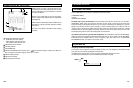
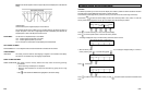
Using Graphing Multimeter (GMM)
Making Connections
INPUT A is used for all GMM tests just except the RPM measurement. The probes and test leads to be used depend
on the type of tes
t
performed. When you select
certain GMM
t
ests, a connection help screen will guide you by
pressing HELP ( ). This tells you which probe or test lead to use and where to connect it.
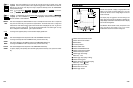
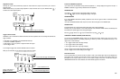
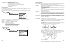
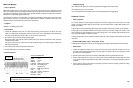
Function Key Labels for Each Test
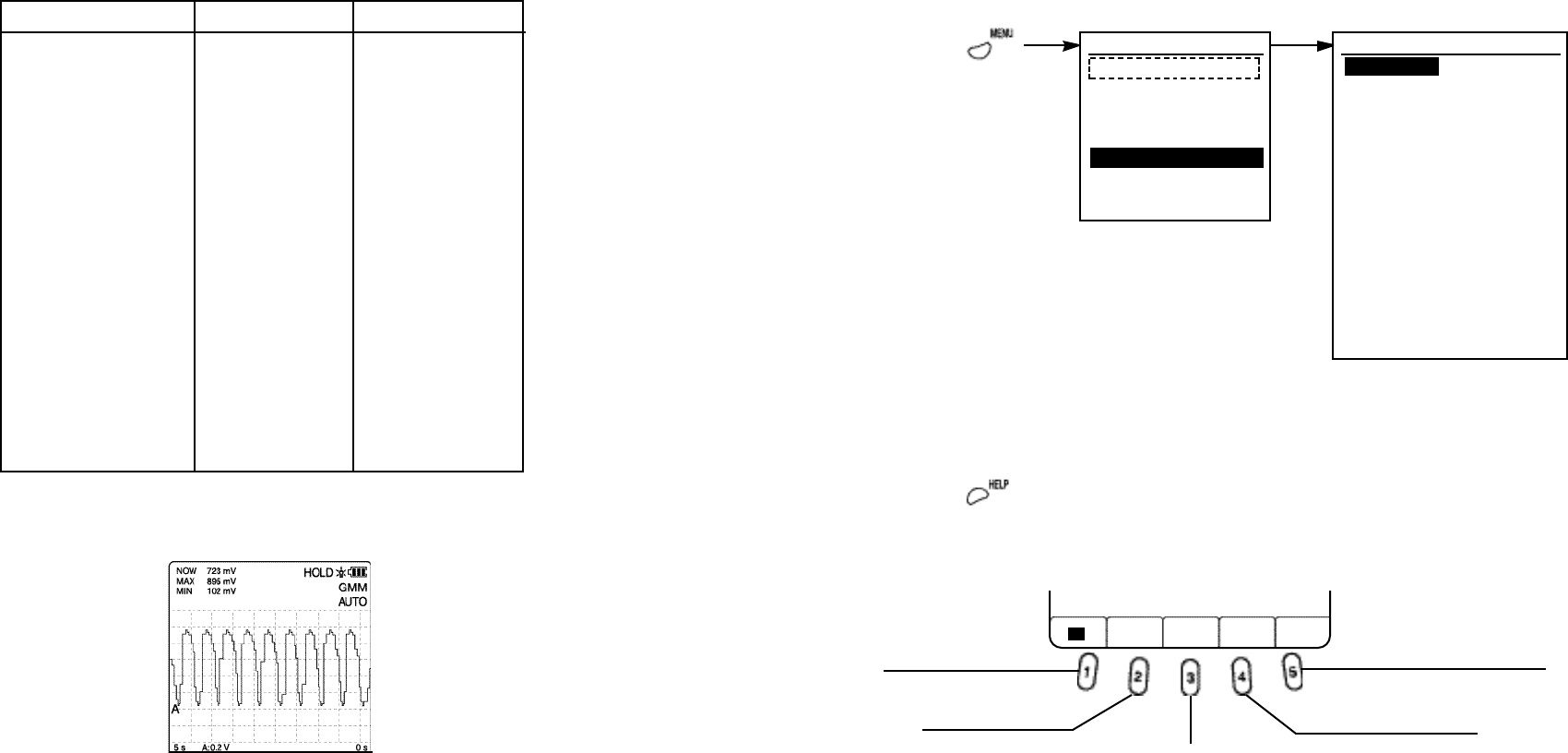
Testing Volt DC, AC
You can stop graphing by pressing HOLD key on the instrument.
5-9
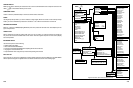
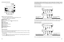
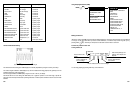
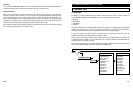
MAIN MENU
SELECTED VEHICLE
CHANGE VEHICLE
COMPONENT TESTS
SCOPE
GRAPHING MULTIMETER
VEHICLE DATA
INSTRUMENT SETUP
GRAPHING MULTIMETER MENU
VOLT DC, AC
OHM / DIODE / CONTINUITY
RPM
FREQUENCY
DUTY CYCLE
PULSE WIDTH
DWELL
IGNITION PEAK VOLTS
IGNITION BURN VOLTS
IGNITION BURN TIME
INJECTOR PEAK VOLTS
INJECTOR ON TIME
AMP DC, AC
TEMPERATURE °C, °F
LIVE
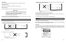
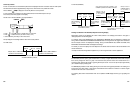
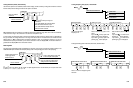
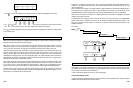
Vertical and Horizontal Scaling
The vertical and horizontal ranges in GMM displays are manually adjustable by using the Four Way arrow keys.
The vertical ranges available in GMM displays vary with the measurement being graphed, and generally cover the
possible output range of the measurement.
The time ranges available for GMM displays range from 5 sec. to 24 hrs. per display.
Auto-Power-Of
f
will not occur during
t
he GMM mode, but to graph
f
or
periods of 5 min and longer,
operate the
instrument from external power because operating endurance on internal power is limited to about 4 hours with fresh
batteries.
5-8
Figure 13. Changing Vertical and Horizontal Ranges
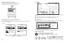
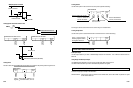
Code
DC VOLT
AC VOLT
AC+DC VOLT
OHM
DIODE
CONTINUITY
RPM
FREQUENCY
DUTY CYCLE
PULSE WIDTH
DWELL
IGNITION PEAK VOLTS
IGNITION BURN VOLTS
IGNITION BURN TIME
INJECTOR PEAK VOLTS
INJECTOR ON TIME
TEMPERATURE
LIVE
Measurement
DC Average
AC Average
AC+DC Average
Ohms
Diode drop
Continuity
RPM
Frequency
Duty Cycle
Pulse Width
Dwell
Ignition Peak Volts
Ignition Burn Volts
Ignition Burn Time
Injector Peak Volts
Injector On Time
Temperature °C, °F
Live
Graphing Type
Continuous
Continuous
Continuous
Continuous
Continuous
Continuous
Cycle by Cycle
Cycle by Cycle
Cycle by Cycle
Cycle by Cycle
Cycle by Cycle
Cycle by Cycle
Cycle by Cycle
Cycle by Cycle
Cycle by Cycle
Cycle by Cycle
Continuous
Direct input samples
MENU ( )
Press to reset maximum
and minimum.
Press to start plotting a new
graph as new samples are
acquired.
Press to measure DC
voltage.
Press to measure AC
true rms voltage.
Press to measure AC+DC true rms voltage.
GMM VOLT
MAX/MIN REPEAT
DC AC AC+DC
RESET TEST