


3. Exercise the switch while paying attention to the amplitude of the signal. It should stay in a predetermined voltage
range for a given condition. In most cases, the amplitude of the waveform should stay at B+ or battery voltage
when the circuit is on, and go to 0 V when the switch is activated.
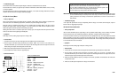
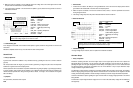
• Reference Waveform
VEHICLE INFORMATIONS
YEAR
:
1993
MAKE : Ford
MODEL : Explorer
ENGINE : 4.0 L
FUELSYS :
Multiport Fuel Injection
PCM_PIN : 2 Lt Grn wire
STATUS : KOER (Key On Running)
RPM : Idle
ENG_TMP
:
Operating Temperature
VACUUM :
19 In. Hg
MILEAGE : 54567
• Troubleshooting Tips
If the waveform has spikes to ground, there may be an open circuit in the power side or a voltage short to ground.
If the waveform has upward spikes, there may be an open in the ground side.
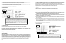
6.5 IGNITION TESTS
6-57
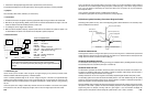
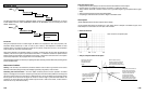
If there is a failure in the circuit, the waveform’s amplitude will change when it is not
supposed to.
MAX = 13.8 V
MIN = -1.0 V
Brake pedal
released
here
Brake pedal
depressed here
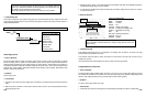
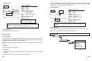
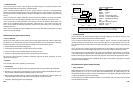
IGNITION
COMPONENT TEST
IGNITION TESTS MENU
PIP/SPOUT
DI Primary
DI Secondary
DIS (EI) Primary
DIS (EI) Secondary
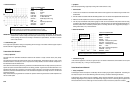
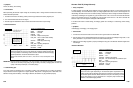
•
Reference Waveform
VEHICLE INFORMATIONS
YEAR
:
1989
MAKE : Buick
MODEL :
Le Sabre
ENGINE : 3.8 L
FUELSYS : Multiport Fuel Injection
PCM_PIN : CH A to speaker (+)
COM to speaker (–)
STATUS : KOEO (Key On Engine Off)
RPM : 0
ENG_TMP : Ambient Temperature
VACUUM
: 0 In. Hg
MILEAGE : 93640
• Troubleshooting Tips
If the speaker is blown, suspect an open circuit.
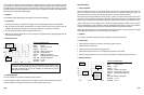
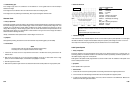
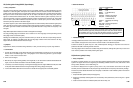
DC Switch Circuits
• Theory of Operation
This test procedure can be applied to a lot of different automotive circuits that use B+ as their power source, such as
power supply circuits (to the PCM and other
control modules),
t
emperature switches,
t
hrottle switches,
vacuum
switches, light switches, brake switches, cruise control switches, etc.
This test can be used to test the integrity of the battery power supply to the switches that rely on the battery power to
operate.
•
Symptoms
No start, lose of power, no working of switches
• Test Procedure
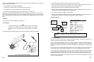
1. Connect the CH A lead to the power supply circuit of the switch to be tested and its ground lead to the switch
GND circuit.
2. Make sure power is switched on in the circuit so that the switch is operational.
6-56
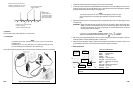
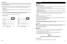
A few notes from Willie Nelson’s
“On The Road Again”
MAX = +473 mV
MIN = -509 mV
music starts new
note here
Automotive speaker
drive signals normally range between 0.5 V and 10
V Peak
t
o
Peak.
Resistance of the speaker voice coils is normally less than 10 ohms.
MENU ( )