


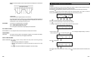
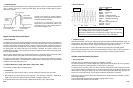
• Reference Waveform
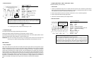
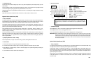
VEHICLE INFORMATION
YEAR : 1987
MAKE : Chrysler
MODEL : Fifth Avenue
ENGINE
:
5.2 L
FUELSYS
:
Feedback Carburetor
PCM_PIN : 5 #1 Org wire + 9 #1 Blk wire
STATUS : KOER (Key On Running)
RPM : 1400
ENG_TMP : Operating Temperature
VACUUM : 19 In. Hg
MILEAGE
:
140241
• Troubleshooting Tips
Make sure the frequency of the waveform is keeping pace with engine RPM, and that the time between pulses only
changes when a “sync” pulse is displayed. This time changes only when a missing or extra tooth on the reluctor
wheel passes the sensor. That is, any other changes in time between the pulses can mean trouble.
Look for abnormalities observed in the waveform to coincide with an engine sputter or driveability problem.
Before assuring the sensor’s failure, when waveform abnormalities are observed, make sure that a chafed wire or
bad wiring harness connector is not the cause, the circuit isn’t grounded, and the proper parts are spinning.
Hall Effect CranKshaft Position (CKP) Sensor
•
Theory of Operation
These CKP sensors are classified as “CKP Sensors-Low Resolution” in industry.
The Hall
CKP sensors are
low resolution
digi
t
al sensors
which generate the CKP signal,
that is a low frequency
(hundreds of Hz) square wave switching between zero and V Ref, from a Hall sensor.
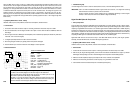
The Hall CKP sensor, or switch, consists of an almost completely closed magnetic circuit containing a permanent
magnet and pole pieces. A soft magnetic vane rotor travels through the remaining air gap between the magnet and
the pole piece. The opening and closing of the vane rotor’s windows interrupt the magnetic field, causing the Hall
sensor to turn on and off like a switch - so some vehicle manufacturers call this sensor a Hall switch.
These sensors operate at different voltage levels depending on the vehicle manufacturers and deliver a series of
pulses as the shaft rotates.
They are used to switch the ignition and/or fuel injection triggering circuits on and off.
The PCM uses the Hall CKP sensors to detect misfire.
6-13
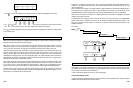
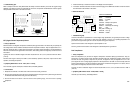
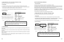
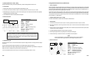
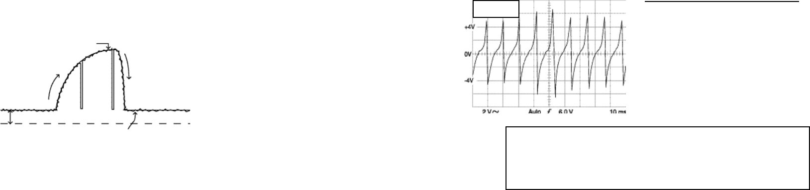
The amplitude and frequency increase with engine speed (RPM).
The amplitude, frequency and shape should be all consistent for the conditions (RPM,
etc.), repeatable (except for “sync” pulses), and predictable.
Generally, the oscillations may not be perfect mirror images of each other above and
below the zero level mark, but they should be relatively close on most sensors.
P - P = 13.7 V
FREQ = 89.2 Hz
• Troubleshooting Tips
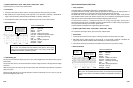
Check the manufacturer’s specifications for exact voltage range. Generally, the sensor output should range from just
under 1 V at idle to just under 5 V at wide open throttle (WOT). There should be no breaks, spikes to ground or
dropouts in the waveform.
Dropouts on
t
he slopes
of the waveform indicate
a
short to ground or an intermittent open in the sensor’s
carbon track (resistance materials).
The firs
t
1/8
t
o 1/3 of the sensor’s carbon track
usually wears out most because this portion is most
used while
driving. Thus,
pay particular attention to
the waveform as it begins to rise.
Magnetic Crankshaft Position (CKP) Sensor
• Theory of Operation
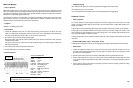
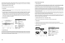
The magnetic CKP sensors are AC signal generating analog sensors. They generally consist of a wire wrapped, soft
bar magnet with two connections. These two winding, or coil, connections are the sensor’s output terminals. When a
ring gear (a reluctor wheel) rotates past this sensor, it induces a voltage in the winding. A uniform tooth pattern on
the reluctor wheel produces a sinusoidal series of pulses having a consistent shape. The amplitude is proportional to
the rotating
speed
of the reluc
t
or
wheel (that is, the crankshaft or camshaft). The frequency is based on the
rotational speed of the reluctor. The air gap between the sensor’s magnetic tip and the reluctor wheel greatly affects
the sensor’s signal amplitude.
They are used to determine where TDC (Top Dead Center) position is located by creating a “synchronous” pulse
which is generated by either omitting teeth on the reluctor wheel or moving them closer together.
The PCM uses the CKP sensors to detect misfire. When a misfire occurs, the amount of time it takes for a waveform
to complete its cycle increases. If the PCM detects an excessive number of misfires within 200 to 1000 crankshaft
revolutions, a misfire code (OBD II DTC) is set.
• Symptoms [OBD II DTC’s: P0340 ~ P0349, P0365 ~ P0369, P0390 ~ P0394]
No or hard start, intermittent misfire, driveability problems
• Test Procedure
1.
Connect the CH A lead to the sensor output or HI and its ground lead to the sensor output LO or GND.
2. With
K
O
E
R (Key On,
Engine
Running), let the engine idle, or use
the throttle to accelerate or decelerate the
engine or drive the vehicle as needed to make the driveability, or emissions, problem occur.
3. Use the Glitch Snare mode to catch dropouts or stabilize waveforms when a “sync” pulse is created.
6-12
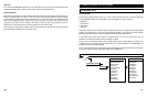
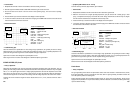
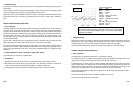
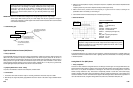
Peak voltage indicates
WOT
Voltage increase
identifies
enrichment.
DC offset indicates voltage
at key on, throttle closed.
Minimum voltage indicates
closed throttle plate.
Voltage decrease
identifies enleanment
(throttle plate closing)
(Defective TPS Pattern)