


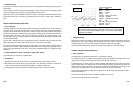
Differential Pressure Feedback EGR (DPFE) Sensor
• Theory of Operation
A
n EGR
(Exhaust Gas Recirculation) pressure sensor is a pressure transducer that tells the PCM the rela
t
ive
pressures in the exhaust stream passages and, sometimes, intake manifold. It is found on some Ford EEC IV and
EEC V engine systems.
Ford calls it a PFE (Pressure Feedback EGR) sensor when the sensor outputs a signal that is proportional to the
exhaust backpressure.
Ford calls it a DPFE (Differential Pressure Feedback EGR) sensor when the sensor outputs the relative difference in
pressure between intake vacuum and exhaust.
These are
important
sensors
because
their
signal input
t
o the PCM is
used to calculate EGR flow
.
A bad EGR
pressure sensor can cause hesitation, engine pinging, and idle problems, among other driveability problems, and I/M
emission test failures.
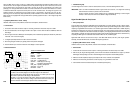
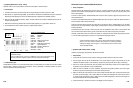
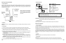
The EGR pressure sensor is usually a three wire sensor. One wire supplies the sensor with 5 V via the PCM’s V Ref
circuit, another wire provides the sensor ground, and the third wire is the sensor’s signal output to the PCM.
Generally, Ford’s DPFE sensors are found on late model 4.0 L Explorers and other vehicles and produce just under
1 V with no exhaust gas pressure and close to 5 V with maximum exhaust gas pressure.
NOTE
Ford’s PFE sensors produce 3.25 V with no exhaust back pressure increasing to
about 4.75
V
with 1.8 PS
I
of exhaust back pressure.
O
n properly operating
vehicles the voltage won’t ever ge
t
to 5
V. PFE sensors can be found on many
Taurus and Sable models.
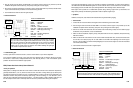
• Symptoms [OBD II DTC’s: P0400 ~ P0408]
Hesitation, engine pinging, idle problems, I/M emission test failure
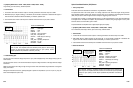
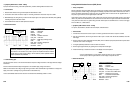
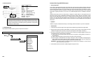
• Test Procedure
1. Connect the CH A lead to the sensor output HI and its ground lead to the sensor output LO or GND.
2. Start the engine and hold
throttle at
2500 RPM for 2–3 minu
t
es until the engine is
f
ully warmed
up and the
Feedback Fuel System is able to enter closed loop. (Verify this by viewing the O
2
sensor signal, if necessary.)
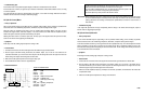
3. Shut off A/C and all other accessories. Drive the vehicle under normal driving modes; start from dead stop, light
acceleration, heavy acceleration, cruise, and deceleration.
4. Make sure that the amplitude is correct,
repeatable, and present
during EGR conditions. The sensor signal
should be proportional to exhaust gas versus manifold vacuum pressures.
5. Make sure that all the hoses and lines to and from the intake manifold, EGR valve, and vacuum solenoid valve
are intact, and routed properly, with no leaks. Make sure the EGR valve diaphragm can hold the proper amount
of vacuum (check manufacturer’s specs.). Make sure that the EGR passageways in and around the engine are
clear and unrestricted from internal carbon buildup.
6. Press the HOLD key to freeze the waveform on the display for closer inspection.
6-31
• Symptoms [OBD II DTC’s: P0100 ~ P0104]
Hesitation, stall, low power, idle problems, excessive fuel consumption, emissions failure
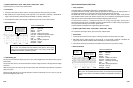
• Test Procedure
1. Connect the CH A lead to the sensor output HI and its ground lead to the sensor output LO or GND.
2. With the Key On, Engine Running (KOER), use the throttle to accelerate and decelerate the engine. Try different
RPM ranges while spending more time in the RPM ranges that correspond to the driveability problem.
3. Make sure that the amplitude, frequency, shape, and pulse width are all consistent, repeatable and accurate for
any given operating mode.
4. Make sure that the sensor generates the correct and steady frequency for a given RPM or airflow rate.
5. Use the Glitch Snare mode to detect dropouts or unstable output frequency.
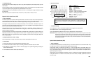
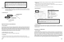
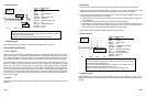
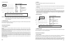
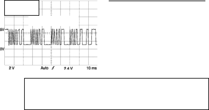
• Reference Waveform
VEHICLE INFORMATIONS
YEAR
:
1992
MAKE : Mitsubishi
MODEL : Eclipse
ENGINE : 1.8 L
FUELSYS : Multiport Fuel Injection
PCM_PIN : 10 GrnBlu wire
STATUS : KOER (Key On Running)
RPM : Snap Acceleration
ENG_TMP
: Operating Temperature
VACUUM
:
3-24 In. Hg
MILEAGE
:
49604
• Troubleshooting Tips
Possible defects to watch for are runted (shortened) pulses, unwanted spikes, and rounded off corners that could all
have the effect of garbling an electronic communication, causing a driveability or emissions problem. The sensor
should be replaced if it has intermittent faults.
6-30
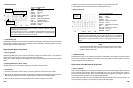
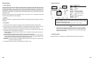
Frequency increases as airflow rate increases. Pulse width (duty cycle) is modulated in
acceleration modes.
Look for pulses that are a
full 5 V in ampli
t
ude.
Look for
t
he proper shape of the
waveform in terms of consistent, square corners, and consistent vertical legs.
FREQ = 69.4 Hz avg.
MAX = 5.06 V
MIN = 933 mV
Karman Vortex MAF sensor
during snap acceleration.