


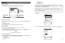
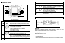
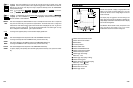
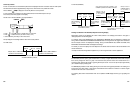
4.7 SCOPE MODE
SC
O
P
E mode provides a
display
of signal patterns from
either CH A or CH B over times ranging from 1 µs to 50
seconds per division, and for voltage ranges from 50 mV
to 300 V full scale.
The display may be
triggered at all time settings, and
trigger slope and level may be adjusted as needed.
The
scope display is defaulted in Glitch Detect mode to display
even the narrowest glitches.
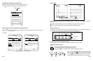
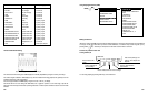
The S
I
NGLE
INPUT SCOPE
mode (Component Tests
only)
provi des for the di splay of up
to four meter
measurements above the waveform viewing area.
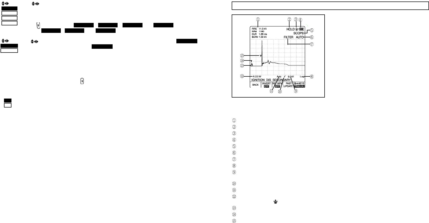
Indicate meter measurement function.
Indicate HOLD function enabled.
Backlit indicator.
Low battery indicator.
Indicate SCOPE mode.
Indicate AUTORANGING mode.
Indicate FILTER function enabled.
Indicate time base per division.
Indicate trigger level voltage.
Blank if DC, ~ if AC.
Indicate trigger slope (rising or falling).
Indicate AUTO triggered.
Indicate voltage per division and coupling.
Blank if DC, ~ if AC, if GND.
Indicate signal source channel.
Indicate INPUT A zero level.
Indicate trigger location.
4-15
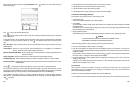
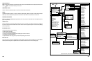
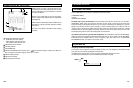
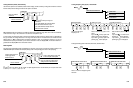
The KEYS icon indicates that you can use the Four Way arrow keys to change Volt & Time
ranges, to move the waveform position, and to adjust the trigger level for either INPUT A or INPUT B.
A
nd also you can use the
Four Way arrow keys to
adjust the sensitivity level in the COMPONENT
TEST (IGNITION mode).
Press to toggle among RANGE A , MOVE A , TRIG LVL , and SENS LVL for INPUT A,
or among RANGE B , MOVE B , and TRIG LVL for INPUT B.
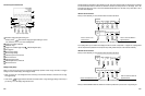
The icon indicates that you can use the Four Way arrow keys to move CURSOR 1 (if CURSOR 1
is highlighted) or move CURSOR 2 (if CURSOR 2 is highlighted). Press the function key to toggle
between CURSOR 1 and CURSOR 2.
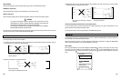
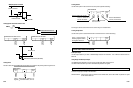
This Label is displayed for SINGLE DISPLAY tests, for example the knock sensor test. To repeat the
test, press the function key, then perform the required action. The knock sensor test is a single shot
measurement, which means that the signal from the knock sensor is displayed only once. To get a new
test result, you have to press the key and then tap the engine block or the sensor again. You may
have to readjust the vertical RANGE to get an optimal waveform.
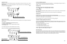
To change to the opposite polarity. Puts the waveform display upside down.
This Label is displayed in the Scope test mode of the COMPONENT TESTS only.
To change from Scope test mode to GMM test mode, press the function key.
This Label is displayed in the GMM test mode of the COMPONENT TESTS only.
To change from GMM test mode to Scope test mode, press the function key.
This Label is displayed in the Scope test of the COMPONENT TESTS only.
To capture, display, and optionally save abnormal signal patterns when they occur, press the function
key.
4-14
REPEAT
TEST
GMM
MODE
SCOPE
MODE
GLITCH
SNARE
KEYS
CURSOR 1
CURSOR 2
KEYS
RANGE A
MOVE A
TRIG LVL
SENS LVL
Figure 9. Scope Mode Indicators
INVERT
OFF
ON