


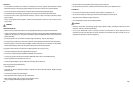
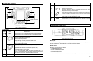
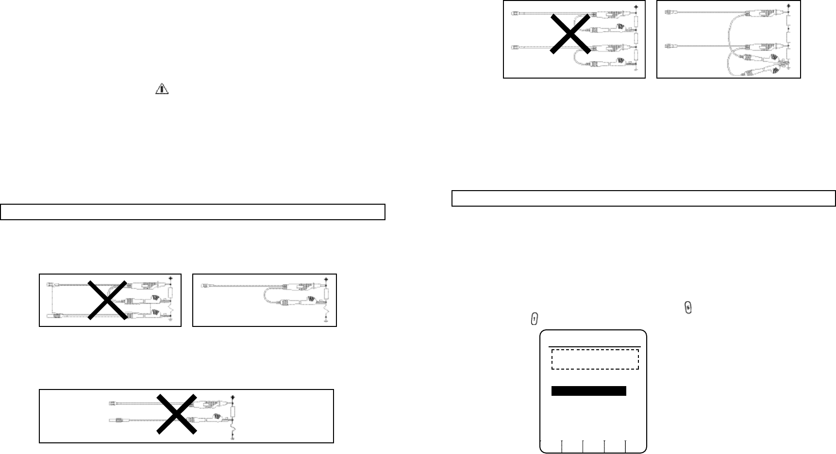
3. Measurement faults or short circuit with the DUAL INPUT SCOPE mode. This occurs when you perform floating
measurements with grounding at different points.
Instrument Grounding for Measurements on the Ignition System
For
t
he instrument safety
,
connec
t
the COM input to engine ground before
you perform
measurements on the
ignition system with the Capacitive Secondary Pickup.
To prevent ground loops, connect all ground leads to the SAME engine ground.
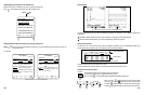
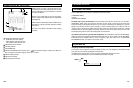
4.6 DISPLAY
The instrument presents “live” measurement data in the form of Scope and GMM displays. Temporary displays are
used to display frozen and saved measurement data.
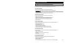
Menus are provided as a means of choosing instrument’s measurement configuration. To display the MAIN MENU
while a measurement display is active, press the MENU key at any time.
Menu Display
When you press MENU key, the instrument displays the MAIN MENU. To select a menu option, use the Four Way
arrow keys to move the highlight bar to the desired item. Then press . To exit the MAIN MENU and return to the
previous setup, press . During menu selection, the bottom part of the screen is used to display the function key
menu.
4-9
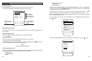
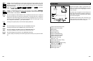
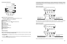
COM, TRIGGER
Used as external trigger for probes with dual banana plugs, such as the RPM Inductive Pickup.
TRIGGER (as single input)
Used in SCOPE mode to trigger (or start) acquisitions from an external source.
COM (as single input)
Used for safety grounding when the Capacitive Secondary Pickup is connected to the ignition system.
WARNING
T O AVOID
ELECTRIC
A
L SHOCK, CONNECT THE COM INPUT OF THE
INSTRUMENT TO VEHICLE GROUND BEFORE CLAMPING THE CAPACITIVE
SECONDARY PICKUP(SUPPLIED) ON THE IGNITION WIRES.
THIS GROUND CONNECTION IS REQUIRED IN ADDITION TO THE NORMAL
MEASUREMENT GROUND CONNECTIONS.
For other tests, the COM input should not be connected to engine ground when the probes have their own ground
connection at the probe end. See the GROUNDING GUIDELINES.
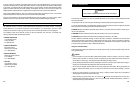
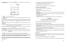
4.5 GROUNDING GUIDELINES
Incorrect grounding can cause various problems:
1. A ground loop can be created when you use two ground leads connected to different ground potentials. This can
cause excessive current through the grounding leads.
2. Excessive noise shown on the measured signal.
4-8
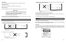
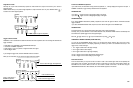
(Incorrect Grounding)
Ground Loop by Double Grounding on
Different Grounds
(Incorrect Grounding)
Noise Pickup on Unshielded Ground Lead
(Correct Grounding)
Shield of Test Lead Connected to Ground
INPUT A
INPUT A
COM
INPUT A
COM
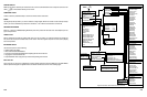
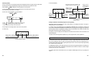
(Incorrect Grounding)
Short Circuit by Grounding on Different
Potentials
(Correct Grounding)
Grounding at One Point
INPUT A
INPUT A
INPUT B
INPUT B
MAIN MENU
SELECTED VEHICLE
( Y e a r , M a k e , L i n e , W D , E n g i n e , e t c . )
CHANGE VEHICLE
COMPONENT TESTS
SCOPE
GRAPHING MULTIMETER
VEHICLE DATA
INSTRUMENT SETUP
BACK SELECT