


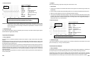
• Test Procedure
1. Connect the CH A lead to the GND pin of the grounded device or the one side of the suspect junction and its
ground lead to the chassis GND or the other side of the suspect junction.
2. Make sure power is switched on in the circuit so that the sensor, device, or circuit is operational and current is
flowing through the circuit.
3. The average voltage drop across the junction should be less than 100 mV to 300 mV.
• Reference Waveform
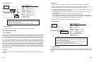
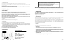
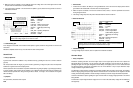
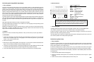
VEHICLE INFORMATIONS
YEAR
:
1986
MAKE : Oldsmobile
MODEL : Toronado
ENGINE : 3.8 L
FUELSYS : Multiport Fuel Injection
PCM_PIN : CH A on Engine Block
COM on Battery Negative
STATUS : KOER (Key On Running)
RPM : Idle
ENG_TMP
:
Operating Temperature
VACUUM : 18 In. Hg
MILEAGE
: 123686
• Troubleshooting Tips
If average voltage drop is excessive, clean or replace the connections and cables.
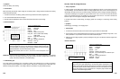
Alternator Output
• Theory of Operation
Alternators replaced generators due
to their higher
output at low engine speed, and their more compact and
lightweight design
.
An alternator is an AC generator with diode rectification, which converts the AC
signal to a
pulsating DC signal. The DC signal charges the vehicle’s battery and supplies power to run the vehicle’s electrical
and electronic systems. Field current is supplied to the rotor in the alternator to vary its output. Alternator output
voltage increases as engine RPM increases.
The alternator’s output voltage is controlled by a solid state regulator within the PCM, in some cases. The regulator
limits the charging voltage to a preset upper limit and varies the amount of the excitation current supplied to the field
winding. The field winding excitation is varied according to the battery’s need for charge and ambient temperature.
Check the manufacturer’s specs regarding the upper and lower limits of charging voltage permitted for the vehicle
being checked.
The alternator’s output voltage should be roughly 0.8 V to 2.0 V above the static battery voltage with the KOEO (Key
Off Engine Off).
6-51
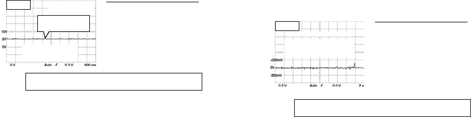
Average voltage drop should not exceed 100 - 300 mV. If there is too much resistance
in the ground circuit, the waveform’s amplitude will be too high.
MAX = 40 mV
MIN = -40 mV
CH A probe connected to engine block
COM probe connected to battery negative.
Test conducted w/engine running.
Tests voltage drop across ground circuit
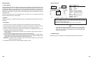
2. Make sure power is switched on to the PCM and monitor the voltage level of the V Ref signal from the PCM.
Compare it with the manufacturer’s recommended limits.
3. If the voltage level is unstable or the waveform shows spikes to ground, check the wiring harness for shorts or
intermittent connections.
•
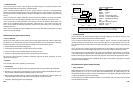
Reference Waveform
VEHICLE INFORMATIONS
YEAR
:
1986
MAKE : Oldsmobile
MODEL : Toronado
ENGINE : 3.8 L
FUELSYS : Multiport Fuel Injection
PCM_PIN :
C14 Gry wire at TPS
STATUS : KOER (Key On Running)
RPM : Idle
ENG_TMP : Operating Temperature
VACUUM
: 18 In. Hg
MILEAGE : 123686
• Troubleshooting Tips
If the voltage level is unstable or the waveform shows spikes to ground, check the wiring harness for shorts or bad
connections.
Waveform’s amplitude should not vary more than 200 mV under normal operation.
Ground Circuit
• Theory of Operation
A ground circuit con
t
rols the feedback on any con
t
rolled circuit
by grounding that circuit to a common conductor
(ground).
This
test procedure tests the integrity of ground circuits by per
f
orming a voltage drop test across the suspected
resistance in a ground circuit or the suspect junction.
This test procedure can be used assure components and devices are getting the quality of ground supply necessary
for proper operation. This procedure can be applied to a lot of different automotive circuits that are grounded to the
vehicle’s electrical systems either through the engine block, chassis, or through a wire connected to the negative
side of the battery.
•
Symptoms
Poor performance, inaccurate sensor outputs
6-50
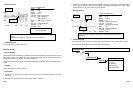
The voltage should
s
t
ay in a predetermined vol
t
age
range for a given condi
t
ion.
Normal V Ref voltage ranges are from 4.50 V to 5.50 V.
MAX = 5.33 V
MIN = 4.66 V
Waveform’s amplitude should
not vary more than 200 mV
under normal operating modes
wiggle the sensor harness/wiring
while watching the waveform’s
amplitude to check for bad
connections or chafed wires
Sensor Reference Voltage -
sent out by PCM. Supplies
voltage to various sensors.